Poe power receiving method and poe power receiving device

A receiving method and receiving device technology, applied in the direction of data switching current source, data exchange details, advanced technology, etc., can solve problems such as security, data transmission characteristic degradation, data loss, etc.

Inactive Publication Date: 2017-12-05
GUANGDONG VTRON TECH CO LTD
View PDF5 Cites 3 Cited by
  • Summary
  • Abstract
  • Description
  • Claims
  • Application Information

AI Technical Summary

Problems solved by technology

[0005] The existing method of increasing the power of POE power supply is mainly to increase the output voltage or output current of the PSE power supply equipment. Although this method can achieve power improvement to a certain extent, the technical problems faced are: First, the current carrying capacity of the cable and The problem of heat dissipation reduces the life of the insulation layer of the cable, and there are potential safety hazards; the second is the increase of the DC current in the data transformer, and the small resistance imbalance in the parallel power supply path causes an offset current in the transformer, which will reduce the inductance of the transformer. This reduction in inductance will degrade the data transmission characteristics, and, in severe cases, it will lead to a high bit error rate (BER) or complete loss of data, especially in the Gigabit Ethernet environment.

Method used


Image

  • Poe power receiving method and poe power receiving device
  • Poe power receiving method and poe power receiving device

Examples


Embodiment Construction

[0019] The specific implementation manner of the POE power receiving method of the present invention will be described in detail below in conjunction with the accompanying drawings.

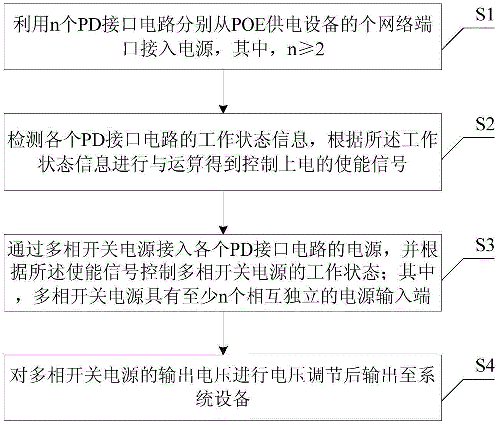
[0020] refer to figure 1 as shown, figure 1 It is a flow chart of the POE power receiving method of an embodiment, including the following steps:

[0021] Step S1: Use n PD interface circuits to respectively access power from n network ports of the POE power supply device, where n≥2.

[0022] In this step, a PD interface circuit of a common POE power receiving device may be used, and the PD interface circuit mainly implements functions such as PD device detection, power classification, power rectification, and power management.

[0023] Step S2: Detect the working state information of each PD interface circuit, and perform an AND operation according to the working state information to obtain an enabling signal for powering on the system equipment.

[0024] In this step, the corresponding level...


PUM


Abstract

The present invention provides a PoE power supply receiving method and a PoE power supply receiving device, wherein the method includes the step of accessing a power source from the N network ports of the PoE power supply device using N PD interface circuitry, wherein N ≥ 2; detects each PD interface.The working status information of the circuit is performed according to the working state information to obtain an enable signal to control power-on, and the output power source of each PD interface circuit is accessed by the multi-phase switching power source, and the multi-phase switch is controlled according to the enable signal.The power supply status of the power supply; wherein the multi-phase switching power source has at least n mutually independent power input; outputting the output voltage of the multi-phase switching power supply to the system device.The technical solution of the present invention can increase the power supply power of the PoE device without affecting data transmission, and it is possible to effectively support the power supply reception security, and improve the operation stability of the system equipment.

Description

technical field [0001] The present invention relates to the technical field of power supply over Ethernet, in particular to a POE power receiving method and a POE power receiving device. Background technique [0002] POE (Power over Ethernet) Power over Ethernet technology refers to the transmission of data signals for some IP-based terminal equipment while the existing Ethernet Cat.5 cabling infrastructure does not make any changes. Technology for supplying DC power to such devices (system devices). The advantages of POE power supply are: 1. Simple installation, simple wiring, no need to arrange power lines, only need to arrange Ethernet cables to realize power supply to system equipment; 2. In some special network environments (such as elevated), no It is convenient to arrange the power cord / power adapter, and the power supply within 100M can be easily realized by using the Ethernet cable. [0003] At present, there are two specifications for POE power supply, IEEE802.3a...

Claims


Application Information

Patent Timeline
Patent Type & Authority Patents(China)
IPC IPC(8): H04L12/10
CPCY02D30/50
Inventor 康万龙王晓芳夏卫忠
Owner GUANGDONG VTRON TECH CO LTD
Why Eureka
Try Eureka