Check patentability & draft patents in minutes with Patsnap Eureka AI!

Point-on-wave controller with at least three monitored inputs

A point-on-wave controller and parameter input technology, applied to electrical components, electronic switches, electric switches, etc., can solve problems such as unrealizable switching strategies

Active Publication Date: 2016-06-08
HITACHI ENERGY SWITZERLAND AG
View PDF4 Cites 0 Cited by
  • Summary
  • Abstract
  • Description
  • Claims
  • Application Information

AI Technical Summary

Problems solved by technology

[0009] However, all described implementations have the disadvantage that an appropriate switching strategy is not possible in all cases, e.g. in the case of two loads in a 11 / 2CB layout when the properties of one load change or two loads It is not possible to implement an appropriate switching strategy when all properties of

Method used


Image

  • Point-on-wave controller with at least three monitored inputs
  • Point-on-wave controller with at least three monitored inputs
  • Point-on-wave controller with at least three monitored inputs

Examples


Embodiment Construction

[0035] Overview:

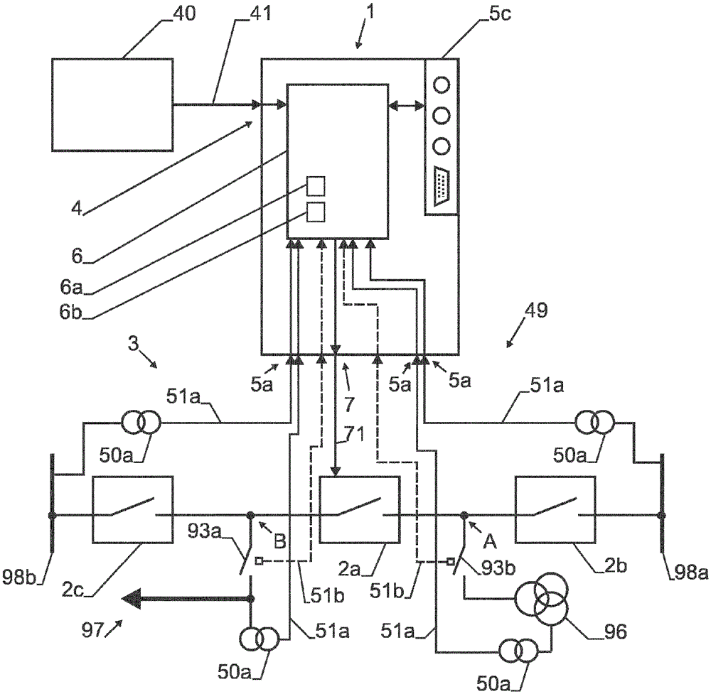
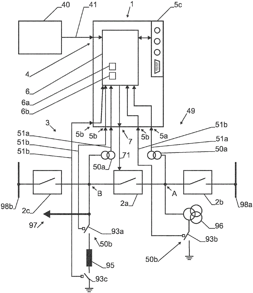
[0036] A point-on-wave controller for a network synchronous switch of a circuit breaker arrangement in an AC power transmission network comprising at least three monitoring interfaces is disclosed. A plurality of operating parameters of the power transmission network are used for the circuit breaker arrangement and during calculation of an improved operating strategy for the circuit breaker arrangement a reference signal is selected.

[0037] definition:

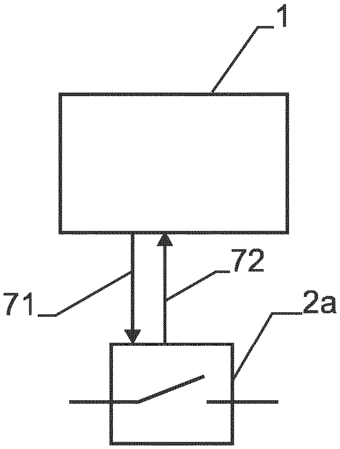
[0038] The point-on-wave controller 1 is a controller device of the circuit breaker devices 2a, 2b, 2c in the AC power transmission network 3, which determines a suitable operating strategy, typically after receiving an external switching command 41 from the switching command issuing device 40, And an actual circuit breaker switching command is issued in order to actually perform the switching action by said circuit breaker arrangement 2a, 2b, 2c. A certain phase 47a, 47b, 47c, 48a, 48b, 52a, 52b of an o...


PUM


Abstract

A point-on-wave controller (1) for network synchronous switching of circuit breaker devices (2a, 2b, 2c) in an AC power transmission network (3) is disclosed, said point-on-wave controller comprising at least three Monitor interfaces (5a, 5b, 5c). A plurality of operating parameters of the power transmission network (3) are used to select a reference signal for the point-on-wave controller (1) and during calculation of an improved operating strategy for the circuit breaker arrangement (2a, 2b, 2c) .

Description

technical field [0001] The present invention relates to a point-on-wave controller device and method for controlling the operation of circuit breaker devices, in particular circuit breaker devices in AC power transmission networks, and power transmission networks comprising circuit breaker devices and wave cables Point the controller's compartment. Background technique [0002] To minimize switching transients during operation of circuit breakers (CBs) in power transmission networks, controlled switching of CBs (point-on-wave (POW) control, also called "synchronous switching") is state of the art. In short, CB operation is delayed in such a way that contact touching / disengaging and / or starting / stopping current flow will occur at points of time well suited to the CB, the load of the switch and / or the network. This point in time is usually chosen as a specific phase angle of the primary voltage or current in the network. For example, for capacitive loads, a well-suited energ...

Claims


Application Information

Patent Timeline
Patent Type & Authority Patents(China)
IPC IPC(8): H03K17/16H03K17/28H01H9/56
CPCH03K17/28H01H9/56H03K17/165
Inventor M.斯塔内克A.塔鲁里
Owner HITACHI ENERGY SWITZERLAND AG
Features
  • R&D
  • Intellectual Property
  • Life Sciences
  • Materials
  • Tech Scout
  • Unparalleled Data Quality
  • Higher Quality Content
  • 60% Fewer Hallucinations
Learn More