Method and system for subnetwork connection protection

A technology of seed network and protection domain, which is applied in the direction of transmission system, optical transmission system, electromagnetic wave transmission system, etc., and can solve the problem that the protection function cannot be completed normally

Inactive Publication Date: 2014-01-15
ZTE CORP
View PDF3 Cites 2 Cited by
  • Summary
  • Abstract
  • Description
  • Claims
  • Application Information

AI Technical Summary

Problems solved by technology

[0008] The technical problem to be solved by the present invention is to provide a subnet connection protection method and system to solve the problem that the protection function cannot be completed normally in some specific scenarios of the existing protection type

Method used


Image

  • Method and system for subnetwork connection protection
  • Method and system for subnetwork connection protection
  • Method and system for subnetwork connection protection

Examples


Embodiment Construction

[0034] In order to make the purpose, technical solution and advantages of the present invention more clear, the embodiments of the present invention will be described in detail below in conjunction with the accompanying drawings. It should be noted that, in the case of no conflict, the embodiments in the present application and the features in the embodiments can be combined arbitrarily with each other.

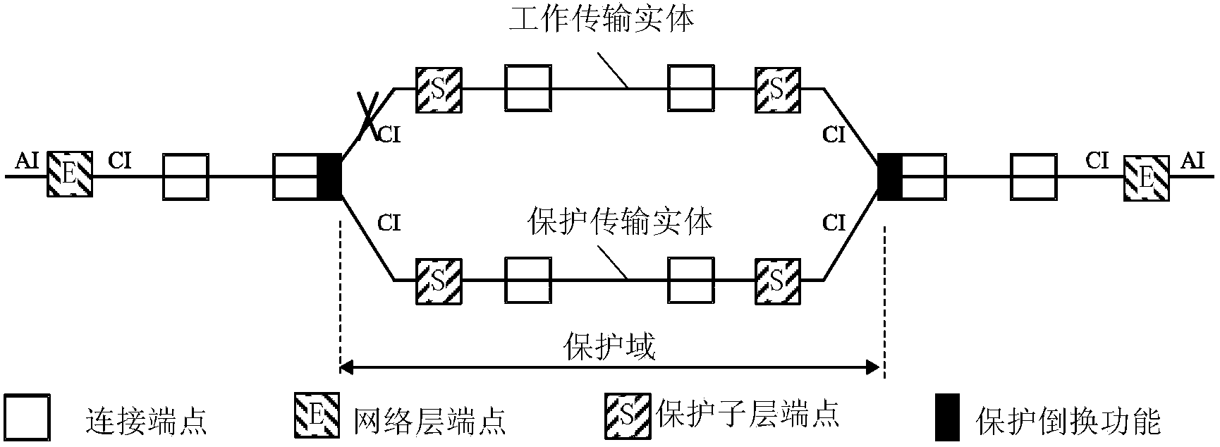
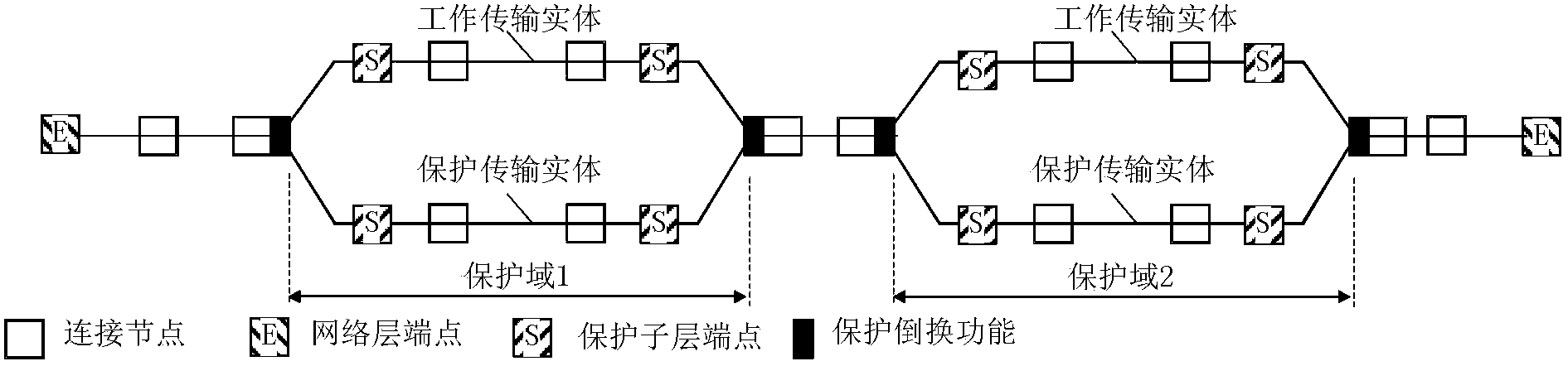
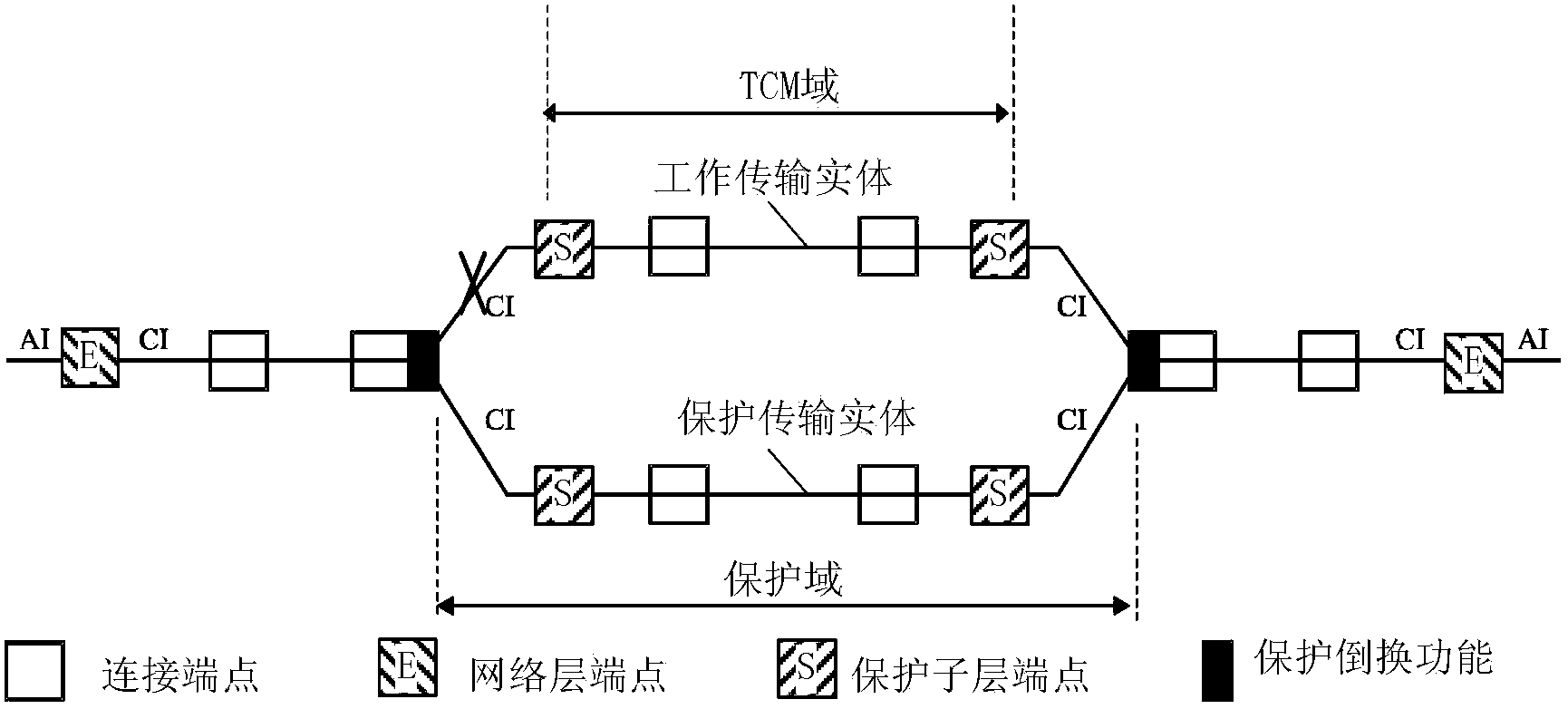
[0035] An embodiment of the present invention provides a subnet connection protection method, including:

[0036] The extended fault monitoring domain is consistent with the protection domain, and corresponding alarms are added to the extended part of the fault monitoring domain;

[0037] After the source node detects the failure of the extended part, it generates the added alarm, and sends the alarm information to the sink node;

[0038] After the sink node monitors the alarm, it executes protection switching as a condition for the protection switching to take effect.

[0...


PUM


Abstract

Provided in the invention is a method for subnetwork connection protection. The method comprises the following steps that: a fault monitoring domain is expanded to be consistent with a protection domain and a corresponding alarm unit is added at the expanded portion of the fault monitoring domain; after a source node detects a fault at the expanded portion, the added alarm is generated and the alarm information is sent to a destination node; after the destination node monitors the alarm, protection switching is executed based on a protection switching entry-into-force condition. In addition, the invention also provides a system for subnetwork connection protection. According to the method and the system, fault monitoring on all nodes can be carried out, thereby realizing protection switching correctly.

Description

technical field [0001] The invention relates to the protection technology of optical transmission network. A method and system for SNC (Subnetwork Connection, subnetwork connection) protection are provided. Background technique [0002] In G.808.1, subnet protection in linear protection is defined, such as figure 1 shown. The biggest feature of the subnet is that it can provide cascading protection for multiple protection domains, and a failure in each protection domain will not affect other protection domains, such as figure 2 shown. [0003] However, in actual equipment, there are some problems in the use of the above model, such as image 3 shown. It can be found that the protection domain and the TCM (Tandem Connection Monitoring, tandem connection monitoring) domain are not completely overlapped, and there are some differences at both ends. And if a failure occurs in these different places ( image 3 middle X position), then there will be problems with the prote...

Claims


Application Information

Patent Timeline
Patent Type & Authority Applications(China)
IPC IPC(8): H04B10/032H04B10/075
CPCH04B10/07H04B10/032H04B2210/071H04J3/14H04J3/1652H04J2203/0051H04J2203/006
Inventor 王东
Owner ZTE CORP
Why Eureka
Try Eureka