Handle locking structure and electronic equipment possessing the handle locking structure

A locking structure and handle technology, applied to the circuit layout of the support structure, electrical equipment shell/cabinet/drawer, wing leaf handle, etc., can solve the problems of inconvenient use and inconvenient operation

Active Publication Date: 2014-01-15
HONOR DEVICE CO LTD
View PDF2 Cites 13 Cited by
  • Summary
  • Abstract
  • Description
  • Claims
  • Application Information

AI Technical Summary

Problems solved by technology

In order to prevent the chassis from loosening, there is a buckle structure on the chassis. If the chassis needs to be pulled out from the rack, the operator needs to pull the buckle structure with one hand, and pull the chassis out of the rac

Method used


Image

  • Handle locking structure and electronic equipment possessing the handle locking structure
  • Handle locking structure and electronic equipment possessing the handle locking structure
  • Handle locking structure and electronic equipment possessing the handle locking structure

Examples


Embodiment 1

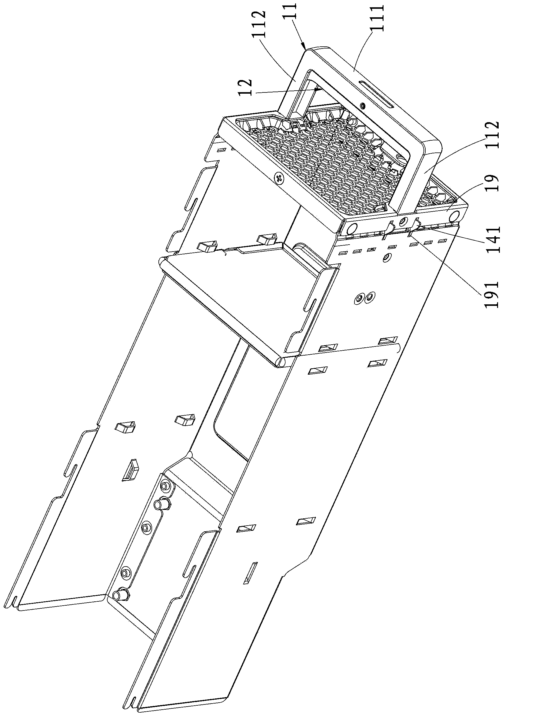
[0021] The handle locking structure provided by the embodiment of the present invention can be applied to electronic devices such as servers and communication devices. The electronic equipment may include a rack and a case, and the case is arranged on the rack.

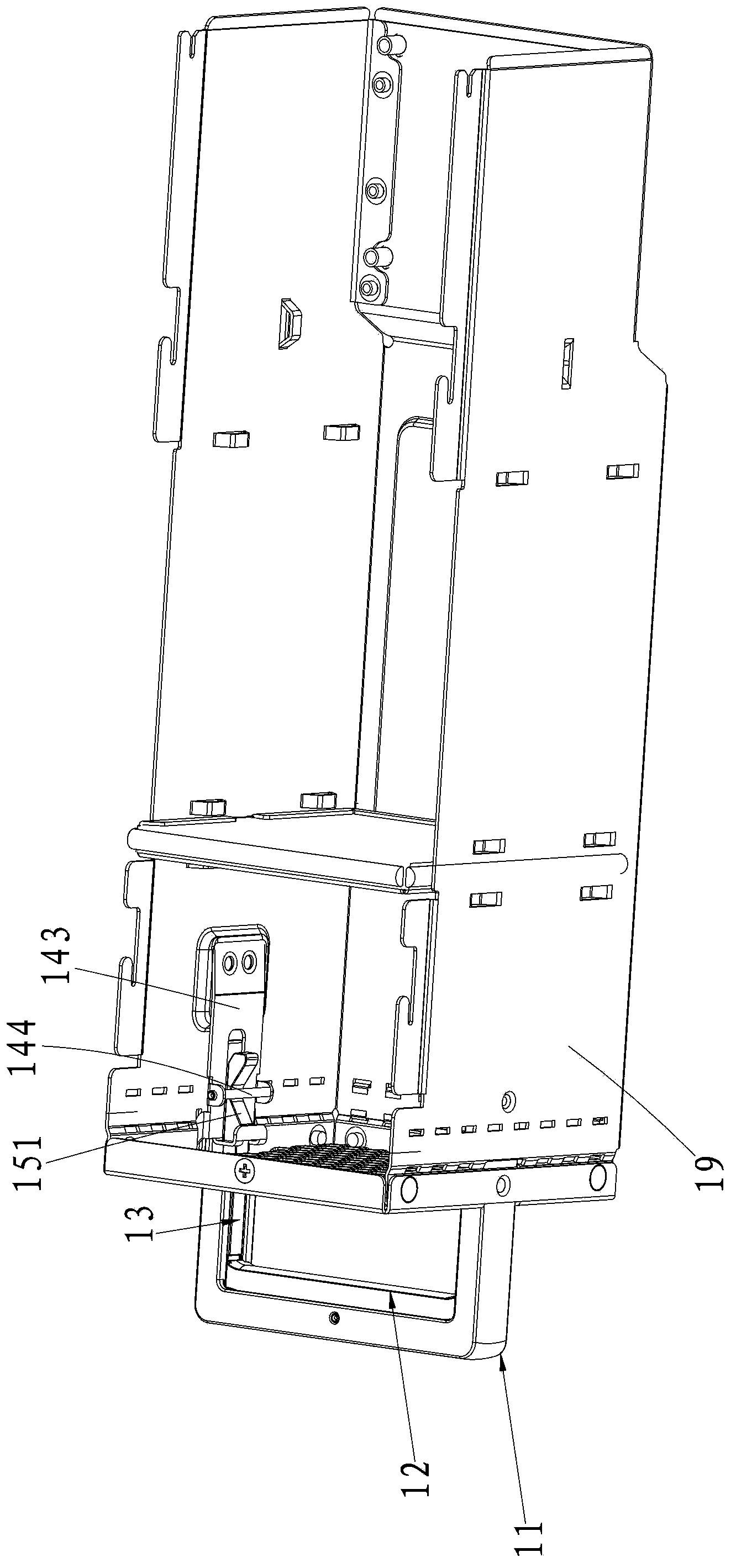
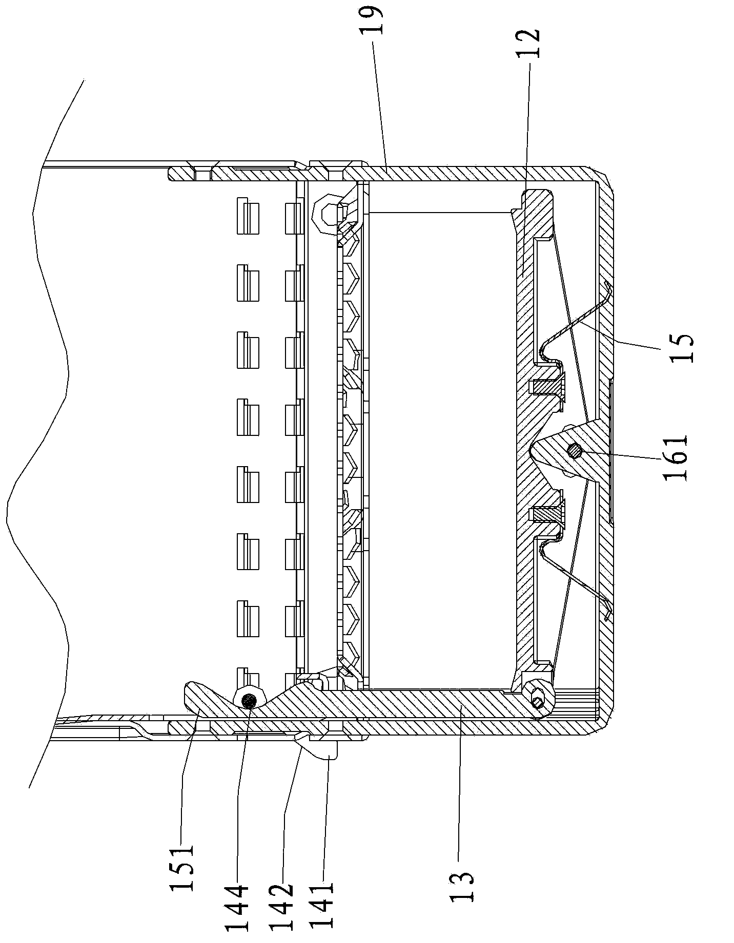
[0022] Such as figure 1 and figure 2 As shown, the above-mentioned handle locking structure includes a handle body 11 , a pressing member 12 , a transmission member 13 connected to the pressing member 12 , and a locking part that can be driven by the transmission member 13 .

[0023] Among them, such as figure 1 and figure 2 As shown, the handle body 11 can be fixedly connected to the casing 19 of the case, and the operator can hold the handle body 11 to facilitate inserting the case into the rack or pulling the case out from the rack. The pressing member 12 is slidably or rotatably connected to the handle body 11. The operator can easily press the pressing member 12 while holding the handle body 11. It can be o...

Embodiment 2

[0040] The handle locking structure provided by the embodiment of the present invention can be applied to electronic devices such as servers and communication devices. The electronic equipment may include a rack and a case, and the case is arranged on the rack.

[0041] Such as Figure 7 and Figure 8 As shown, the above-mentioned handle locking structure includes a handle body 21 , a pressing member 22 , a transmission member 23 connected to the pressing member 22 , and a locking component that can be driven by the transmission member 23 .

[0042] Among them, such as Figure 7 and Figure 8 As shown, the handle body 21 can be connected to the casing of the case, and the operator can hold the handle body 21 to insert the case into the rack or pull the case out from the rack. The pressing member 22 is slidably or rotatably connected to the handle body 21 , and the operator can press the pressing member 22 while holding the handle body 21 , which can be operated with one ha...


PUM


Abstract

The invention is suitable for a handle structure technology field in electronic equipment and discloses a handle locking structure and electronic equipment possessing the handle locking structure. The handle locking structure comprises a handle body connected to a shell, a pressing component, a transmission component and a locking component, wherein the pressing component, the transmission component and the locking component are slidingly or rotatably connected to the handle body. The locking component comprises a spring bolt. The transmission component is connected to the pressing component. An unlocking structure used for making the spring bolt retract is arranged between the transmission component and the locking component. The transmission component is connected to the spring bolt through the unlocking structure. Through pressing the pressing component, the transmission component can slide. The slidable transmission component acts on the spring bolt through the unlocking structure so that the spring bolt is retracted. The electronic equipment comprises a rack. The rack is provided with a chassis. The chassis is provided with the handle locking structure. By using the handle locking structure and the electronic equipment possessing the handle locking structure provided in the invention, operation is convenient and user usage is convenient.

Description

technical field [0001] The invention belongs to the technical field of handle structures in electronic equipment, and in particular relates to a handle locking structure with a locking function and electronic equipment with the handle locking structure. Background technique [0002] At present, an electronic device, such as a rack server, includes a rack and a case, and the case is plugged into the rack. In order to facilitate pulling out the case from the rack, a handle is provided on the casing of the case for easy gripping. In order to prevent the chassis from loosening, there is a buckle structure on the chassis. If the chassis needs to be pulled out from the rack, the operator needs to pull the buckle structure with one hand, and pull the chassis out of the rack through the handle with the other hand. Inconvenient to operate. The handles in the electronic equipment in the prior art are mostly made of stainless steel round rods bent and welded to the casing, which is n...

Claims


Application Information

Patent Timeline
IPC IPC(8): H05K5/02H05K7/10
CPCH05K7/1411E05B1/00E05B65/46E05C1/08E05C1/12H05K5/0221H05K5/023H05K7/1415H05K7/1489Y10T292/097
Inventor 梁旭飞郑光明
Owner HONOR DEVICE CO LTD
Why Eureka
Try Eureka