Check patentability & draft patents in minutes with Patsnap Eureka AI!

Electronic device shell locking structure and demounting method thereof

A technology for electronic devices and housings, which is applied to electrical equipment shells/cabinets/drawers, circuits, telephone communications, etc., and can solve problems such as difficult disassembly and difficult maintenance of electronic devices.

Inactive Publication Date: 2014-01-29
SHENZHEN FUTAIHONG PRECISION IND CO LTD
View PDF0 Cites 2 Cited by
  • Summary
  • Abstract
  • Description
  • Claims
  • Application Information

AI Technical Summary

Problems solved by technology

The body of the electronic device is locked by a buckle structure, and although the screw positioning assembly is firm, these fixing methods are more difficult to disassemble, which will cause difficulties for future maintenance of the electronic device

Method used


Image

  • Electronic device shell locking structure and demounting method thereof
  • Electronic device shell locking structure and demounting method thereof
  • Electronic device shell locking structure and demounting method thereof

Examples


Embodiment Construction

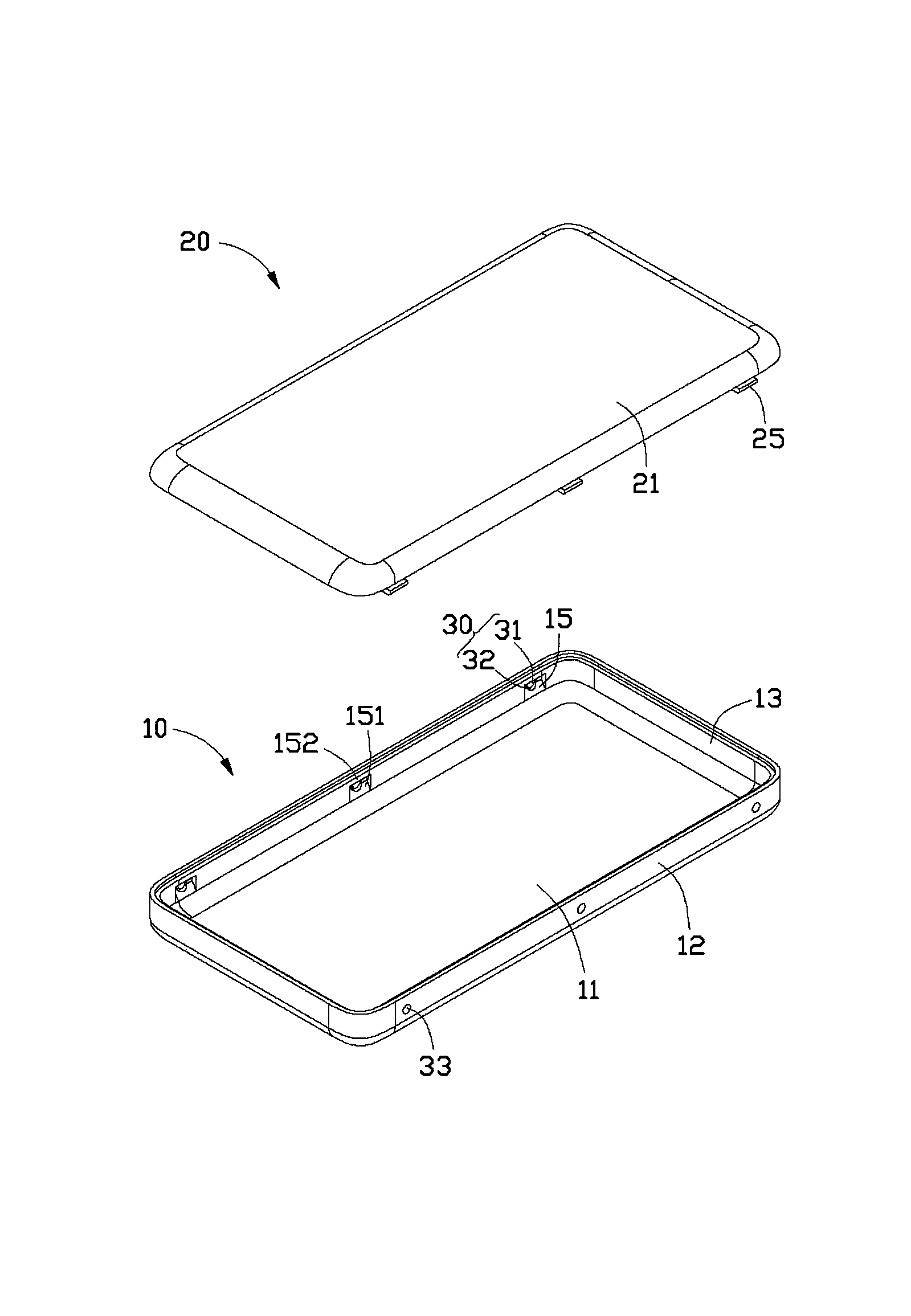
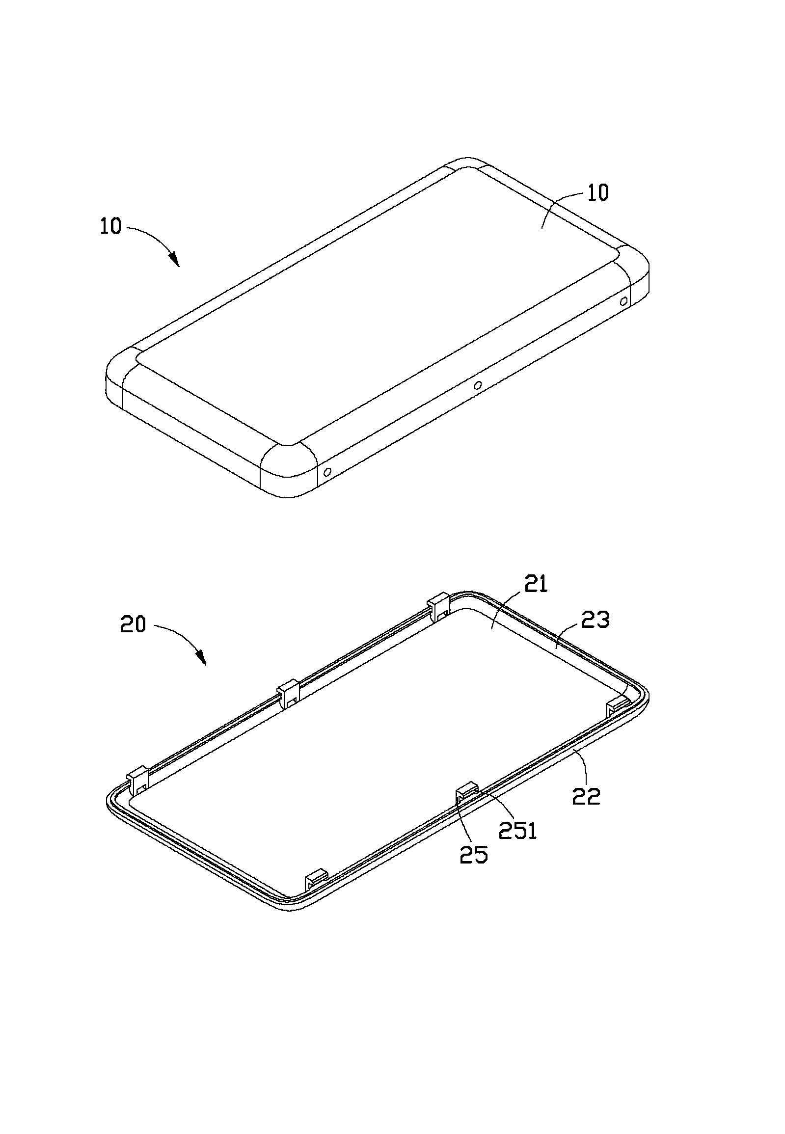
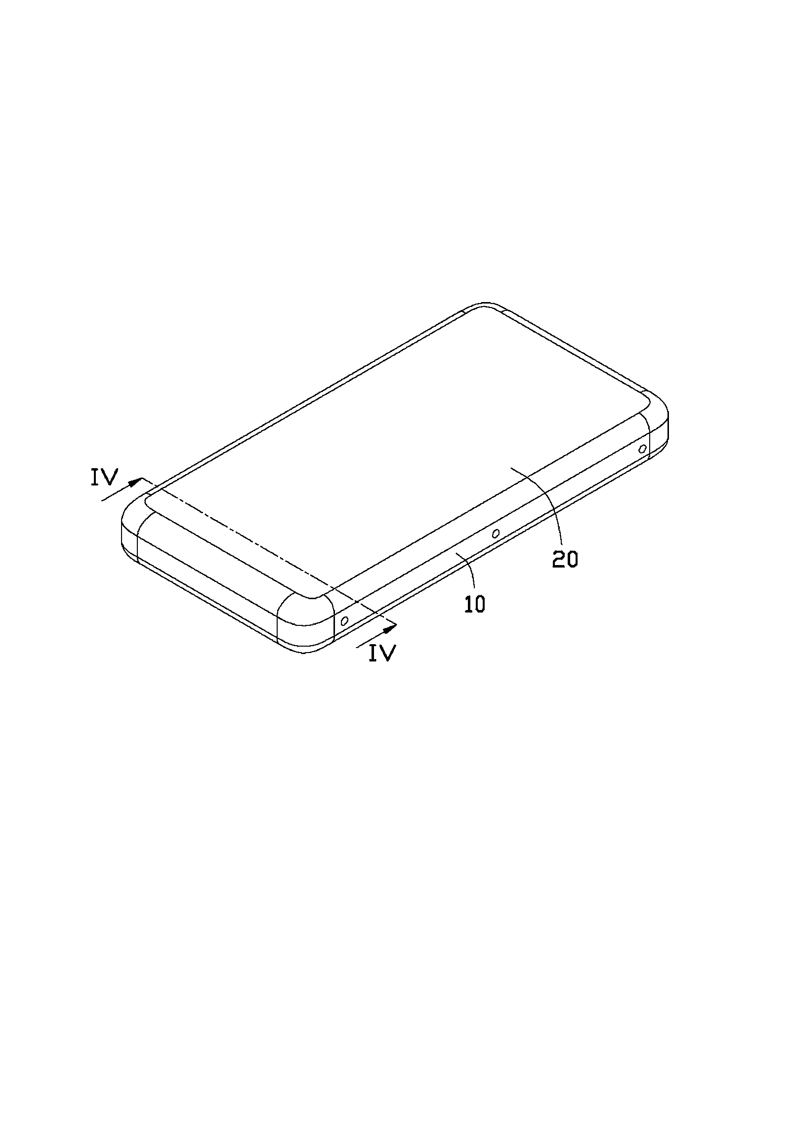
[0020] see figure 1 and figure 2 The housing locking structure of the electronic device of the present invention includes a first body 10, at least two card slots 15 disposed on the first body 10, a second body 20, at least two hooks 25 disposed on the second body 20, and The detachment part 30 corresponding to the row of the card slots 15 . The second body 20 is covered on the first body 10 , and is held by the holding portion 25 through the slot 15 , and a pin pushes against the dismounting portion 30 , and then the pin pushes the hook portion 25 out of the slot 15 , the first body 10 and the second body 20 are unlocked.

[0021] The first body 10 can be a casing, which includes a bottom wall 11 , two opposite side walls 12 and two opposite end walls 13 . The two side walls 12 are respectively connected to the two end walls 13 . In this embodiment, there are six card slots 15 , and every three card slots 15 are arranged on the inner surface of the side wall 12 at interv...


PUM


Abstract

An electronic device shell locking structure comprises a first body, a second body, at least two clamp grooves formed in the first body and hooks parts disposed on the second body and clamped to the clamp grooves. The shell locking structure further comprises demounting parts. Each demounting part comprises a demounting body disposed in the corresponding clamp groove and a shallow groove formed on the periphery of the demounting body. When each demounting body is pushed by external force, the corresponding shallow groove breaks to allow the demounting body to be disconnected with the corresponding clamp groove, the clamp groove is allowed to be communicated with the outside, and each hook part can be disconnected with the corresponding clamp groove. The invention further provides a demounting method of the electronic device shell locking structure.

Description

technical field [0001] The invention relates to a casing locking structure applied to an electronic device and a dismounting method thereof. Background technique [0002] In the prior art, the body assembly of portable electronic devices such as mobile phones is held by a buckle structure or assembled by screws. The buckle structure is that a buckle is provided on one housing of the body, and a slot is provided on the other housing, and the buckle and the slot are clamped to assemble and fix the two housings. The body of the electronic device is locked by a buckle structure, and although the screw positioning assembly is firm, these fixing methods are relatively difficult to disassemble, which will cause difficulties for future maintenance of the electronic device. Contents of the invention [0003] In view of the above problems, it is necessary to provide a locking structure for an electronic device housing that is easy to disassemble. [0004] It is also necessary to p...

Claims


Application Information

Patent Timeline
Patent Type & Authority Applications(China)
IPC IPC(8): H05K5/02
CPCH05K5/0221H05K5/0013H05K13/00H04M1/0252Y10T29/49815Y10T403/59
Inventor 钟焕章杨刚秦中树
Owner SHENZHEN FUTAIHONG PRECISION IND CO LTD
Features
  • R&D
  • Intellectual Property
  • Life Sciences
  • Materials
  • Tech Scout
  • Unparalleled Data Quality
  • Higher Quality Content
  • 60% Fewer Hallucinations
Learn More