A load isolating switch

A technology for isolating switches and loads, applied in the field of load isolating switches, can solve the problems of long power supply time on both sides, inability to operate with load, train suspension operation, etc., and achieve the effect of reducing the number of transmission parts, reducing the arc area, and reducing the electric repulsion

Active Publication Date: 2016-04-27
武汉长海电气科技开发有限公司
View PDF4 Cites 0 Cited by
  • Summary
  • Abstract
  • Description
  • Claims
  • Application Information

AI Technical Summary

Problems solved by technology

[0003] Existing isolating switches, whether electric or manual, cannot be operated under load
In order to ensure equipment and personal safety, necessary operation interlocks should be set up. In the actual operation of the subway, there are too many interlock conditions for operating the electric isolating switch. Problems with train suspension

Method used


Image

  • A load isolating switch
  • A load isolating switch
  • A load isolating switch

Examples


Embodiment Construction

[0021] The present invention will be described in further detail below in conjunction with the accompanying drawings.

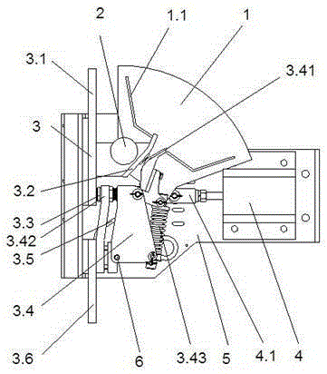
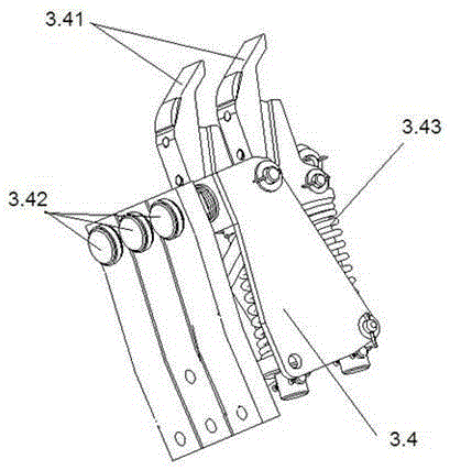
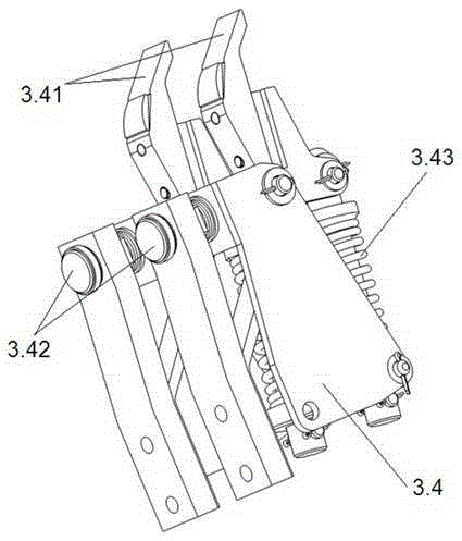
[0022] refer to figure 1 , figure 2 with image 3 As shown, the present invention discloses a load isolating switch, which includes an insulating frame 5, an operating mechanism 4 fixed on the frame 5, a contact system 3 and an arc extinguishing chamber 1. The arc extinguishing chamber 1 is a grid-type extinguishing chamber. The arc chamber and the two ends of the arc extinguishing chamber 1 are provided with a magnetic blowing coil 2, and the magnetic blowing coil 2 and the arc extinguishing chamber 1 are arranged side by side at both ends of the frame 5, and a magnetic guide plate is fixed on the outside of the magnetic blowing coil 2, so that when the switch breaks the load, The arc connects the magnetic blow coil into the main circuit in series, so that the magnetic blow coil generates a magnetic field that is beneficial to the extinguishment of the ar...


PUM


Abstract

The invention discloses a load disconnecting switch. The load disconnecting switch comprises an insulating frame and an operating mechanism fixed on the frame, a contact system and an arc extinguish chamber, and magnetic blow-out coils are arranged at the two ends of the arc extinguish chamber. The contact system comprises a static contact base, a static arc contact and a static main contact, the static arc contact and the static main contact are fixed on the static contact base, a shaft is arranged at the bottom of the static contact base, a dynamic contact is installed on the shaft, a dynamic arc contact, a dynamic main contact and a spring are fixed on the dynamic contact, the static arc contact is arranged between the magnetic blow-out coils and the dynamic arc contact, the static arc contact is connected with a static arc strike angle, the magnetic blow-out coils are connected with the static arc strike angle and the static contact base, the dynamic contact is connected with a flexible coupling through the dynamic contact base, and the operating mechanism is connected with the dynamic contact through a pushing rod. The load disconnecting switch has the advantages that a fault large current is conducted, a rated load current is disconnected, the load disconnecting switch can bear a large current within a short time, the structure is compact, working is safe and reliable, and the load disconnecting switch is suitable for an urban railway system direct current traction power supply system and serves as a longitudinal load operating power-driven disconnecting switch.

Description

technical field [0001] The invention relates to a load isolating switch, in particular to an isolating switch which can be operated under load. Background technique [0002] At present, most domestic subways are equipped with longitudinal electric isolating switches at the traction network section to ensure the implementation of large bilateral power supply when the traction substation is disconnected. [0003] No matter the existing isolating switch is electric or manual, it cannot be operated under load. In order to ensure equipment and personal safety, necessary operation interlocks should be set up. In the actual operation of the subway, there are too many interlock conditions for operating the electric isolating switch. The problem of suspension of train operation. [0004] If a load isolating switch is designed to replace the existing electric isolating switch, all interlocking conditions will be cancelled, and the dispatcher can operate the longitudinal load isolati...

Claims


Application Information

Patent Timeline
Patent Type & Authority Patents(China)
IPC IPC(8): H01H33/18
Inventor 乐洪有马子文郝德清
Owner 武汉长海电气科技开发有限公司
Why Eureka
Try Eureka