Balancing device used for transition draw gear

A transition coupler and balance device technology, which is applied in transportation and packaging, railway vehicle body parts, railway vehicle coupling accessories, etc., can solve the problems of close coupler damage, adverse effects on the vehicle body, and increase the speed of the coupling. long life effect

Active Publication Date: 2015-01-07
CRRC QINGDAO SIFANG ROLLING STOCK RES INST
View PDF5 Cites 0 Cited by
  • Summary
  • Abstract
  • Description
  • Claims
  • Application Information

AI Technical Summary

Problems solved by technology

[0003] The existing transitional coupler does not have a balancing device. During field application, due to the large gap between the No. 15 and No. 13 couplers, the close-fitting hook end of the transitional coupler will "bow its head" under the action of its own weight after installation, making the close-fitting hook end It is not easy to connect with the official coupler, and the connection speed must be increased to successfully connect
This will not only easily cause damage to the close coupler, but also may have a certain adverse effect on the car body
[0004] At the shunting operation site, some shunting workers temporarily add wood chips or iron sheets to the underside of the 15 / 13 hook coupling surface, which can alleviate the "head bowing" phenomenon to a certain extent, but this method is not easy to operate and cannot fundamentally Solve the problem

Method used


Image

  • Balancing device used for transition draw gear
  • Balancing device used for transition draw gear
  • Balancing device used for transition draw gear

Examples


Embodiment 1

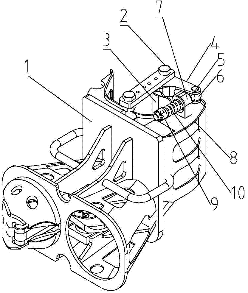
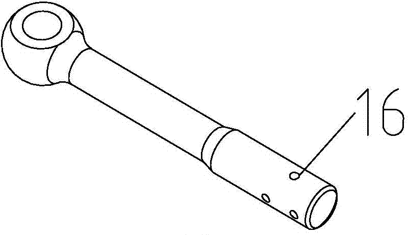
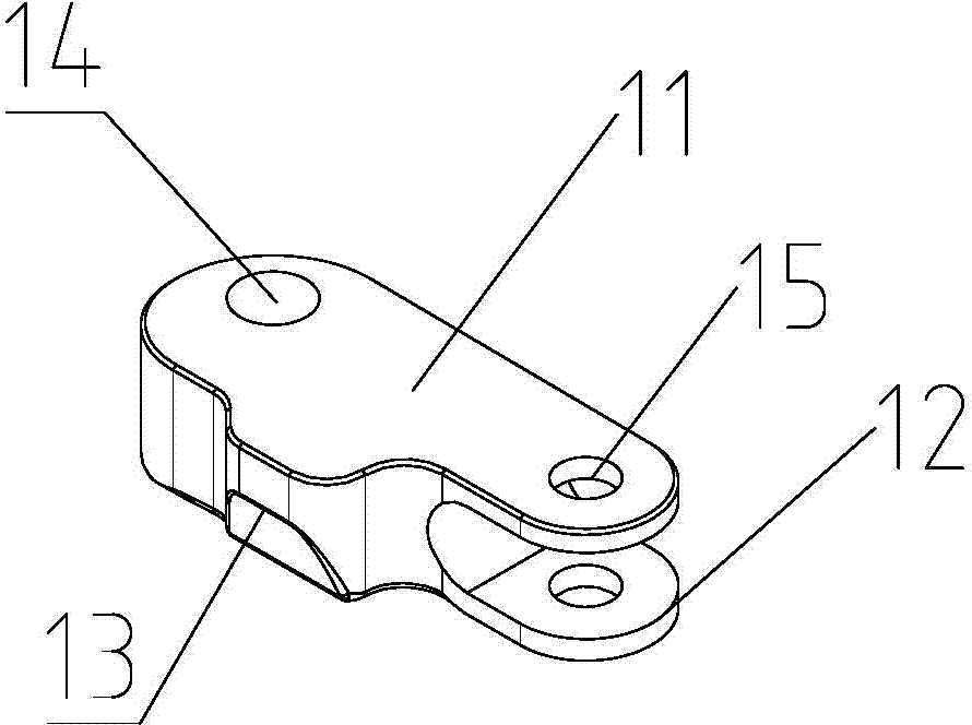
[0026] Such as Figure 1 to Figure 4 As shown, the balance device for the transition coupler is arranged on the upper end surface of the transition coupler 1, and the balance device for the transition coupler includes a rotating shaft 2, a rotating rod 4 and a top seat 7 arranged on the transition coupling 1; the rotating rod 4 includes an upper end plate 11 and the lower end plate 12, the lower end plate 12 is provided with an inclined platform protrusion 13, the inclined platform protrusion 13 is located on the side of the lower end plate, and the inclined platform protrusion 13 is a piece of raised structure, with the upper end plate 11 of the rotating rod 4 With reference to the lower end plate 12, the longitudinal direction of the inclined table protrusion 13 is a structure inclined outward to the rotating rod 4. One end of the rotating rod 4 is installed on the rotating shaft 2, and the other end of the rotating rod 4 is equipped with a pin shaft 5, and on the pin shaft 5...

Embodiment 2

[0036] Because the specific shapes of different types of couplers are also different, it is different from Embodiment 1, and the structure of the rotating rod has been further improved. Between the horizontal positions of the connecting holes 15. This design is applicable to other types of transition couplers, and the position of the connecting hole 14 of the rotating shaft can be designed according to the specific shape of the coupler.


PUM


Abstract

A balancing device used for a transition draw gear is arranged on the upper end face of the transition draw gear. The balancing device comprises rotating shafts, a rotating rod and a top base, wherein the rotating shafts, the rotating rod and the top base are arranged on the transition draw gear. The rotating rod comprises an upper end plate and a lower end plate, wherein a sloping embossment is arranged between the upper end plate and the lower end plate, the sloping embossment is located on a side face of the lower end plate and of a one-piece protruding structure, by taking the upper end plate and the lower end plate of the rotating rod as the reference, the sloping embossment is of a structure of inclining out of the rotating rod in the longitudinal direction, one end of the rotating rod is arranged on one of the rotating shafts, the other end of the rotating rod is provided with a hinge pin, a swing bolt is further arranged on the hinge pin, and the rotating rod can rotate around the one of the rotating shafts and hinged to the swing bolt through the hinge pin. A through hole is formed in the top base, the swing bolt penetrates through the through hole of the top base, the tail end of the swing bolt is fixedly provided with a nut, a spring is arranged between the nut and the through hole of the top base, and the diameter of the spring is larger than the diameter of the through hole of the top base. According to the balancing device, the phenomenon that the head of transition draw gear falls when the draw gear is coupled up can be effectively avoided, and the transition draw gear is kept horizontal after being installed.

Description

technical field [0001] The invention relates to a balancing device for a transitional coupler, in particular to a balancing device for a transitional coupler adapted to a 15 / 13th coupler and closely connected to the coupler. Background technique [0002] The transitional coupler is an important device for shunting operations, train return and rescue. In the field of rail vehicles, the transitional coupler with the 15 / 13 coupler adapted to the close-fitting coupler is very common. [0003] The existing transitional coupler does not have a balancing device. During field application, due to the large gap between the No. 15 and No. 13 couplers, the close-fitting hook end of the transitional coupler will "bow its head" under the action of its own weight after installation, making the close-fitting hook end It is not easy to connect with the official coupler, and the connection speed must be increased to successfully connect. This not only easily causes damage to the closely conn...

Claims


Application Information

Patent Timeline
Patent Type & Authority Patents(China)
IPC IPC(8): B61G7/00
Inventor 刘辉段书华刘世
Owner CRRC QINGDAO SIFANG ROLLING STOCK RES INST
Why Eureka
Try Eureka