PCIE (peripheral component interface express) card integrated installation device

A card slot and transfer card technology, applied in the direction of digital processing power distribution, etc., can solve the problems of increased heat dissipation design, high power consumption, high ambient temperature, etc., achieve flexible disassembly, solve heat dissipation problems, and reduce heat dissipation pressure.

Active Publication Date: 2014-02-19
DAWNING INFORMATION IND BEIJING +1
View PDF4 Cites 3 Cited by
  • Summary
  • Abstract
  • Description
  • Claims
  • Application Information

AI Technical Summary

Problems solved by technology

This method has the following disadvantages: 1. The power consumption is large, and the power supply design is difficult; the PCIE card and its PC, server and other computer systems share a power supply, which increases the burden of power supply design
And for such a system, only one power supply is often allowed to be plugged in, so designing a power supply that can support 700W power consumption is still very challenging, and the price is relatively expensive
If more than 2 GPU accelerator cards are supported, the design of the power supply will be more difficult
2. The problem of heat dissipation is difficult to solve; in a computer system, CPU, memory and chipsets are the main heat generating devices. If a high-power PCIE card is inserted, the PCIE card is also a main heat source
For most of the current systems, the PCIE card is located at the air outlet of the entire system, the surrounding temperature is relatively high, and the heat dissipation environment is harsh, which increases the difficulty of heat dissipation design.
3. The size of the PCIE card is limited; PCIE card standards are divided into half-height half-length, full-height half-length, full-height Most computer systems are limited by cost and industry standards, so it is difficult to reserve such a wide space for PCIE cards
In this way, there is a problem that the high performance and space of the PCIE card are mutually restricted.
4. The number of PCIE cards is limited; in order to pursue higher performance of the computer system, people hope to insert more and more PCIE cards. It is possible to insert 1 PCIE card, and in a few cases, 2 PCIE cards can be inserted, and it is rare to insert more PCIE cards

Method used


Image

  • PCIE (peripheral component interface express) card integrated installation device
  • PCIE (peripheral component interface express) card integrated installation device

Examples


Embodiment Construction

[0022] The present invention will be described in further detail below in conjunction with embodiment.

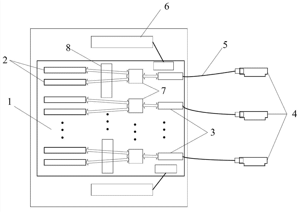
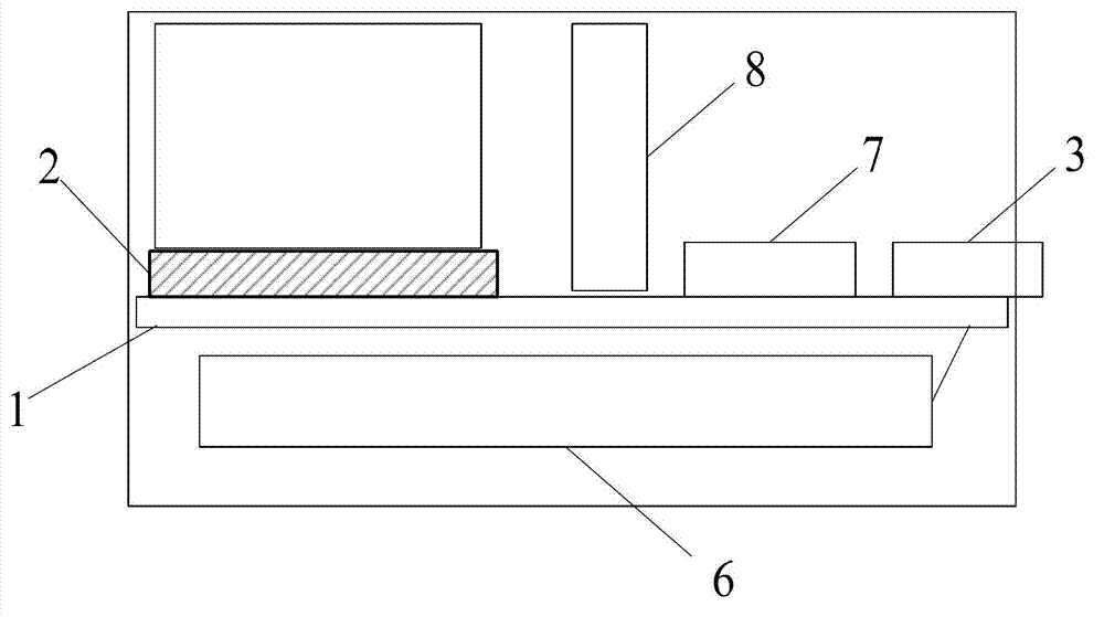
[0023] like figure 1 and figure 2 The shown embodiment, a kind of device that installs PCIE card centrally, comprises backplane 1, the PCIE card slot 2 and PCIE connector 3 that are arranged on the backplane 1, the independent power supply 6 that is connected with backplane 1 and PCIE transfer The card 4 and the PCIE card slot 2 are connected to the PCIE connector 3 through the PCIE bus, and the PCIE connector 3 is connected to the PCIE adapter card 4 through the PCIE cable 5; the backplane 1 is provided with multiple PCIE card slots 2, which can support standard Half height and half length (half height: 68.90mm, half length: 16.70mm), or full height and half length (full height: 111.15mm, half length: 16.70mm), or full height and full length (full height: 111.15mm, half length: 312mm) The PCIE card is inserted, and a PCIE switch chip 7 is also designed on the backboard....


PUM


Abstract

A PCIE (peripheral component interface express) card integrated installation device comprises a back plate, PCIE card slots, PCIE connectors, an independent power supply and PCIE riser cards. The PCIE card slots and the PCIE connectors are arranged on the back plate, and the independent power supply and the PCIE riser cards are connected with the back plate. The PCIE card slots are connected with PCIE bus through the PCIE connectors, and the PCIE connectors are connected with the PCIE riser cards through PCIE cables. By the PCIE card integrated installation device, power can be supplied to a computer system and PCIE cards in a separated manner, the high-power PCIE cards can be supported optionally, the limit of a power supply of the computer system is broken through, multiple power supply designs can be applied, and the difficult problem in power supplying is solved.

Description

Technical field: [0001] The invention relates to a device for installing a PCIE card. Background technique: [0002] The PCIE bus technology has been widely used in computer systems. Recently, Intel has launched the latest generation of Xeon CPU. One of its very important features is to integrate the PCIE bus into the CPU, instead of using bridge chips as before. The group leads to PCIE bus, which shows the importance of PCIE bus technology and the long-term life cycle of PCIE bus. At present, the most common way to use the PCIE bus is to insert a PCIE card into the PCIE slot of a computer system such as a PC or a server, or to place the relevant circuits on the PCIE card on the motherboard by using the LOM (Locate On Motherboard) method. This mode has the following disadvantages: 1. The power consumption is large, and the power supply design is difficult; the PCIE card and its PC, server and other computer systems share a power supply, which increases the burden of power s...

Claims


Application Information

Patent Timeline
IPC IPC(8): G06F1/18
Inventor 郑臣明邵宗有沙超群王英梁发清
Owner DAWNING INFORMATION IND BEIJING
Why Eureka
Try Eureka