Method and device for measuring transmission time of electric signals in double-frequency modulation wire

A technology for transmitting time and electrical signals, which is applied in the direction of measurement and phase measurement. It can solve the problems of complex circuit design, high cost, and limited measurement accuracy by oscilloscopes, and achieve the effects of high degree of automation, large range, and convenient and flexible operation.

Inactive Publication Date: 2014-03-12
HARBIN ENG UNIV
View PDF6 Cites 4 Cited by
  • Summary
  • Abstract
  • Description
  • Claims
  • Application Information

AI Technical Summary

Problems solved by technology

This method has mature technology and high precision, but there are problems such as complicated circuit design and high cost.
[0005] Northwest Institute of Nuclear Technology, Li Xianyou and others proposed to use an oscilloscope to measure the transmission time of the electrical signal in the wire (Li Xianyou, Wei Xuerong, Yu Lijuan, Wang Ling. Using an oscilloscope to accurately measure the transmission line delay time. Nuclear Electronics and Detection Technology. 2010, 30(3):367-369), this method still uses time domain reflectometry, but because the general-purpose instrument-oscilloscope can be used, it is easy to use and low in cost, but at the same time its measurement accuracy is limited by the oscilloscope

Method used


Image

  • Method and device for measuring transmission time of electric signals in double-frequency modulation wire
  • Method and device for measuring transmission time of electric signals in double-frequency modulation wire
  • Method and device for measuring transmission time of electric signals in double-frequency modulation wire

Examples


Embodiment Construction

[0025] The implementation examples of the present invention will be described in detail below in conjunction with the accompanying drawings.

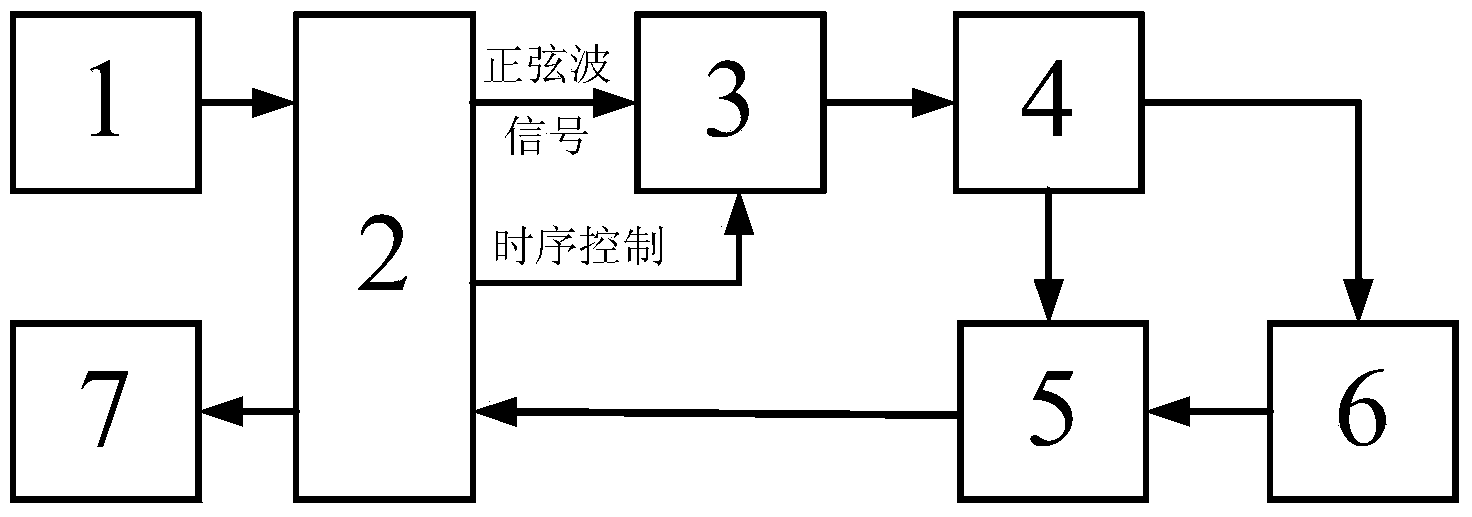
[0026] Part number description in the figure: 1 clock source, 2 master control unit, 3 standard signal generation unit, 4 conditioning amplifier unit, 5 phase difference measurement unit, 6 wire to be tested, 7 display unit.

[0027] A method for measuring the transmission time of an electrical signal in a dual-frequency modulation wire, the method comprising the following steps:

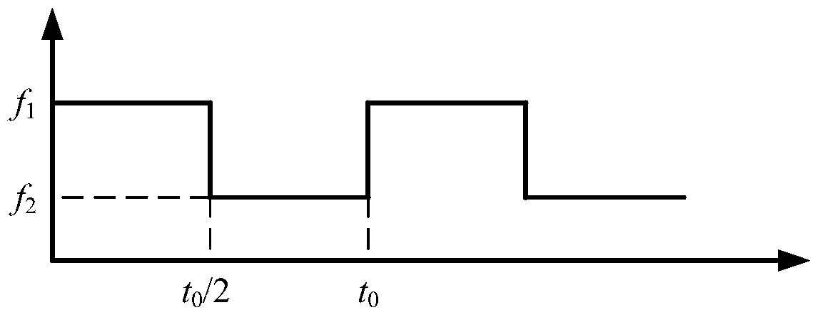
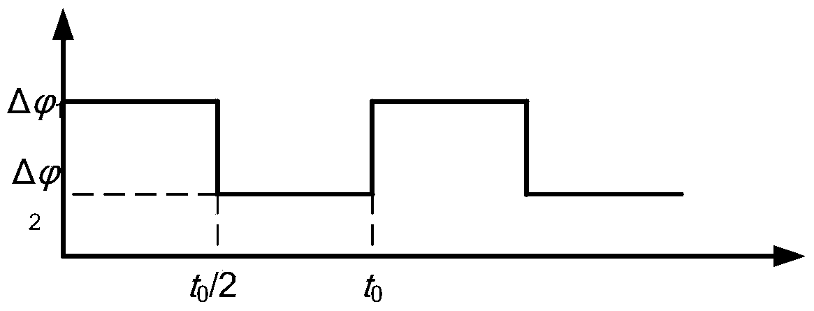
[0028] ①. Controlled by the timing control signal, the modulation frequency is sequentially generated as f 1 (period is T 1 ) and f 2 (period is T 2 ) sine wave signal, which is conditioned and amplified in turn and then divided into two paths, one path as a reference signal directly enters the phase difference measurement unit in turn, and the other path enters the wire to be tested in turn, and then enters the phase difference measurement unit in turn as...


PUM


Abstract

The invention belongs to the field of time measurement and particularly relates to a method and device for measuring the transmission time of electric signals in a double-frequency modulation wire. The device comprises a clock source, a master control unit, a standard signal generation unit, a conditioning and amplifying unit, a phase-difference measuring unit, a wire to be measured and a display unit. The method has the advantages that the period of standard sine wave signals with the high stability is utilized as a scale for transmission of the electric signals in the wire, so that the source tracing can be effectively carried out; the measurement on the transmission time can be carried out by phase difference before and after the standard sine waves with two frequencies are transmitted by the wire, so that the automatic measurement is realized, and simultaneously the resolution, the repeatability and the range of the measurement can be greatly improved.

Description

technical field [0001] The invention belongs to the field of time measurement, in particular to a method and device for measuring the transmission time of electrical signals in a dual-frequency modulation wire. Background technique [0002] Time interval measurement technology is widely used in aerospace, radar positioning, laser ranging, satellite and navigation, atomic physics, mechanical condition monitoring and fault diagnosis, and industrial measurement. In order to accurately calibrate the time interval measurement device, a standard delay line (JJG953-2000 Precision Time Interval Measuring Instrument Verification Regulations) is often used, that is, a wire with a fixed length is used as a standard time interval generator, so that the measurement of the transmission time of the electrical signal in the wire becomes a Difficult question. In order to measure the transmission time of electrical signals in wires, there have been many research methods at home and abroad. ...

Claims


Application Information

Patent Timeline
Patent Type & Authority Applications(China)
IPC IPC(8): G04F10/06
Inventor 钟志单明广史志跃
Owner HARBIN ENG UNIV
Why Eureka
Try Eureka