Strong coupled type power failure current limiter

A power fault and current limiter technology, applied in the direction of inductors, circuits, transformers, etc., can solve the problems of low steady-state impedance, large current limiting impedance, and inability to solve reclosing at the same time for power fault current limiters, and achieves a simple structure. , high reliability and low cost

Active Publication Date: 2014-03-19
TBEA SHENYANG TRANSFORMER GRP CO LTD
View PDF4 Cites 10 Cited by
  • Summary
  • Abstract
  • Description
  • Claims
  • Application Information

AI Technical Summary

Problems solved by technology

[0007] Aiming at the inadequacies of the power fault current limiter in the prior art that cannot well meet the requirements of low steady-state impedance and large current-limiting impedance and cannot solve the problem of resistance recovery when reclosing at the same

Method used


Image

  • Strong coupled type power failure current limiter
  • Strong coupled type power failure current limiter
  • Strong coupled type power failure current limiter

Examples


Embodiment 1

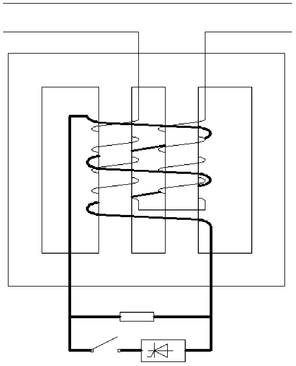
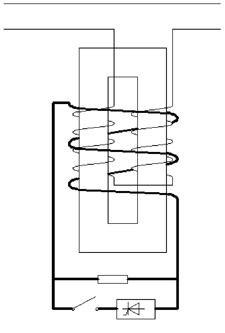
[0035] Such as Figure 1~4 As shown, the strong coupling type power fault current limiter has an iron core and a plurality of coils, and the plurality of coils include AC coils and DC coils; AC coils are respectively wound on a plurality of iron core posts of the iron core. A DC coil is simultaneously wound on the iron core legs of the AC coil; or a DC coil is respectively wound on multiple iron core legs of the iron core, and an AC coil is simultaneously wound on multiple iron core legs wound with DC coils.

[0036] figure 1 In the above two iron core columns, an AC coil (indicated by a thin line) is respectively wound, and the two AC coils are connected in series, that is, the ends of the same name are connected end to end; a DC coil (indicated by a thick line) is wound on the above two iron cores at the same time column. AC and DC have different magnetic flux circuits, and the leakage flux caused by the AC coil can be closed independently, resulting in less additional los...

Embodiment 2

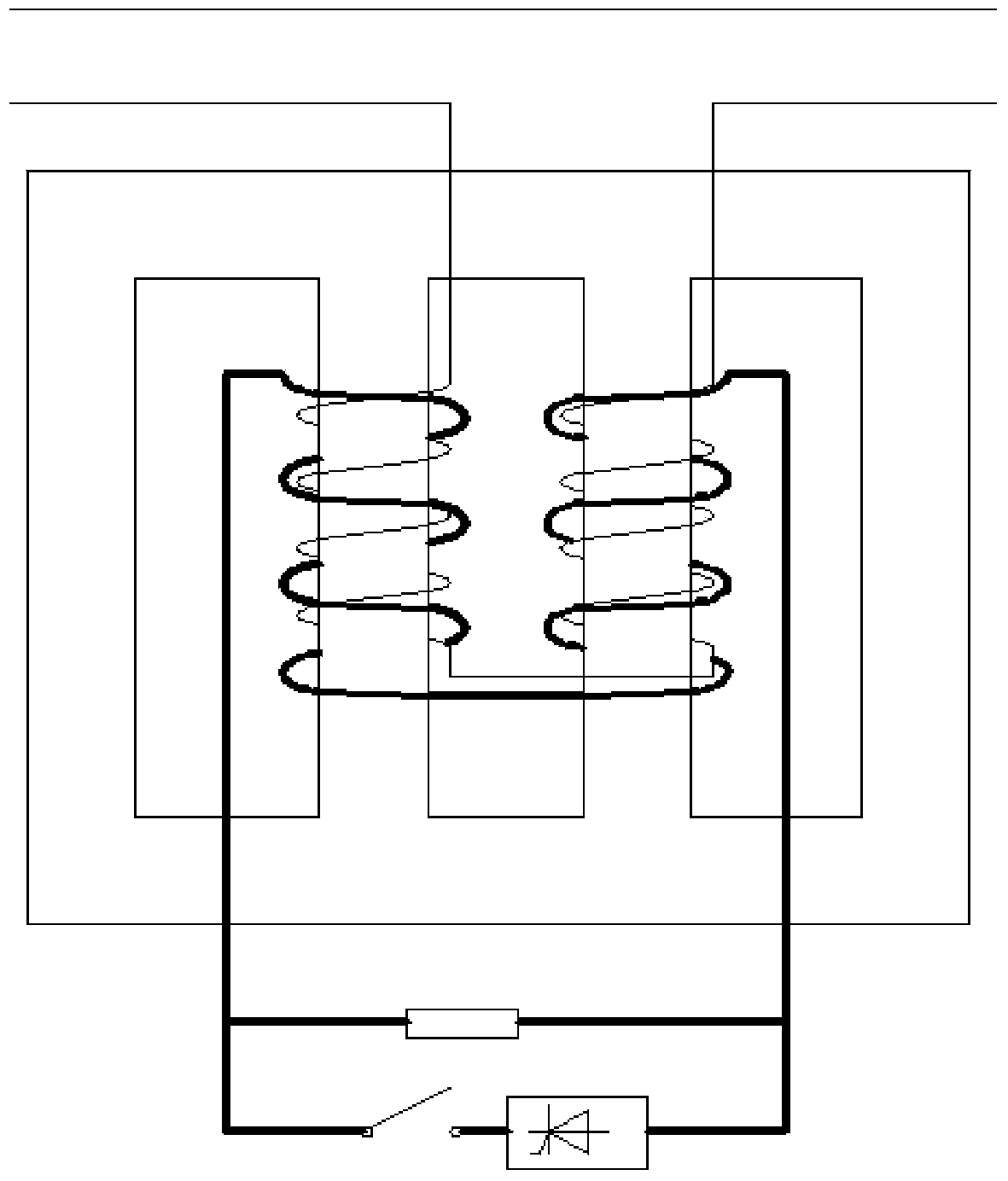
[0047] Such as Figure 5-10As shown, the difference from Embodiment 1 is that there are multiple iron cores and multiple coils, and the multiple coils include AC coils and DC coils; multiple iron core columns of each iron core are respectively wound with AC coils. Coil, a DC coil is wound on multiple iron core columns wound with AC coils at the same time; or DC coils are respectively wound on multiple iron core columns of each iron core, and an AC coil is simultaneously wound on multiple iron core columns wound with DC coils Coils; all AC coils of all iron cores are connected end to end in such a way that the voltage is superimposed; all DC coils of all iron cores are connected end to end in such a way that the AC induced voltages in the DC coils cancel each other out.

[0048] Figure 5 for figure 1 The extended form of , two sets of figure 1 The structure shown is combined in series, with two four-column iron cores, and each of the four core columns is wound with an AC co...


PUM


Abstract

The invention relates to a strong coupled type power failure current limiter. The strong coupled type power failure current limiter is provided with an iron core and a plurality of coils; the plurality of coils comprises alternating current coils and direct current coils; the alternating current coils wind on a plurality of iron coil columns on the iron core respectively and meanwhile a direct current coil winds on the iron core column with the plurality of iron core columns wound on; or the direct current coils wind on the plurality of iron core columns of the iron core respectively and meanwhile an alternating current coil winds on the iron columns with the direct current coils wound on; or the alternating current coils and the direct current coils wind on the plurality of iron core columns of the iron core respectively; more than two alternating current coils are in an end-to-end connection in a mode which enables voltages to be superposed; more than two direct current coils are in end-to-end connection in a mode which enables alternating current voltages inside the direct current coils to be offset mutually. According to the strong coupled type power failure current limiter, a strong couple structure is adopted to satisfy requirements that the impedance is low under normal state and the impedance is large under a short circuit condition, the influence to a system under the normal state is small, a current limit effect is good under a short circuit condition, and a requirement for system reclosing is satisfied.

Description

technical field [0001] The invention relates to a fault current limiting device suitable for power grids, in particular to a strongly coupled power fault current limiter. Background technique [0002] With the development of the power system, the short-circuit capacity of the power system is increasing day by day, and the maximum short-circuit current even exceeds the maximum breaking capacity of the circuit breaker; with the increase of the short-circuit current level, the short-circuit withstand capacity of power transmission and transformation equipment is also required to be further improved. How to limit the excessive short-circuit current in the system has become an urgent problem to be solved. [0003] The common fault current limiters currently used mostly use solid-state switches (usually thyristors), because the operation of solid-state switches will distort the load current, affect the quality of power grid operation, and compensate for high investment costs; And...

Claims


Application Information

Patent Timeline
IPC IPC(8): H02H9/02H01F38/14
Inventor 党艳阳王健安振辛朝辉章海庭
Owner TBEA SHENYANG TRANSFORMER GRP CO LTD
Why Eureka
Try Eureka