Deep Hole Chip Blowing Air Gun

An air gun and deep hole technology, which is applied in the direction of spraying device, liquid spraying device, spraying device, etc., can solve the problem of inability to complete blowing debris

Active Publication Date: 2017-11-03
重庆顺多利机车有限责任公司
View PDF8 Cites 0 Cited by
  • Summary
  • Abstract
  • Description
  • Claims
  • Application Information

AI Technical Summary

Problems solved by technology

The existing problem is that the air nozzle rods of the existing air guns are all fixed-length, and when the debris is stuck in some deep holes or seams, the existing air guns with short nozzle rods cannot complete the cleaning of the debris. Work

Method used


Image

  • Deep Hole Chip Blowing Air Gun

Examples


Embodiment Construction

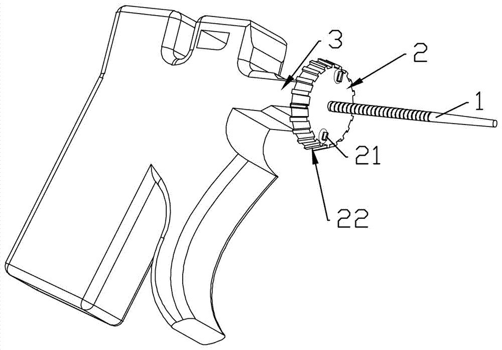
[0008] combined with figure 1 As shown, the body of the deep hole chip blowing air gun is provided with an air nozzle 3, wherein the air nozzle 3 is provided with a mounting head 2, and the mounting head 2 is provided with a variable-length gas nozzle rod 1. The installation head 2 is rotatably connected to the air spray head 3, and the air nozzle rod 1 is screwed to the installation head 2. Anti-slip protrusions 22 are uniformly distributed on the side wall of the mounting head 2 . The installation head 2 is provided with an installation groove 21, and the installation groove 21 is provided with a sealing cover 21. The air spray head 3 is provided with an air guide port opposite to the direction of spraying, and the installation head 2 is fixedly connected with an impeller that matches the two air guide ports. The direction of gas sprayed from the two gas guide ports is opposite to the switch of the gas guide port, and the high-pressure gas is sprayed to realize the forward ...


PUM


Abstract

The invention relates to prevention and removal of common dirt, provides an instrument used for cleaning depressions in a blowing mode by using air jet force, and particularly relates to a deep-hole scrap blowing air gun. The deep-hole scrap blowing air gun comprises a body which is provided with an air jet head, wherein the air jet head is provided with an installation head, and an air faucet rod with the changeable length is arranged on the installation head. The deep-hole scrap blowing air gun can be used for cleaning deep holes or seams.

Description

technical field [0001] The invention relates to the prevention and removal of general dirt, a device for cleaning with air jet force, such as blowing out recesses, in particular to a deep hole chip blowing air gun. Background technique [0002] Air guns are widely used in machining, automobile maintenance and other fields. The air gun is mainly used to blow off the debris generated after machining. The existing problem is that the air nozzle rods of the existing air guns are all fixed-length, and when the debris is stuck in some deep holes or seams, the existing air guns with short nozzle rods cannot complete the cleaning of the debris. Work. Contents of the invention [0003] The object of the present invention is to provide an air gun capable of cleaning relatively deep holes or seams. [0004] The present invention is achieved through the following technical solutions: a deep hole chip blowing air gun, the body is provided with an air nozzle, wherein the air nozzle i...

Claims


Application Information

Patent Timeline
Patent Type & Authority Patents(China)
IPC IPC(8): B08B3/02
CPCB05B1/005B05B9/01
Inventor 邓力
Owner 重庆顺多利机车有限责任公司
Why Eureka
Try Eureka