Fixed light source-type full space distribution luminosity measurement instrument

A full-space, tester technology, used in photometry, optical radiation measurement, instruments, etc., can solve problems such as inability to measure luminous flux, inability to accurately adjust the spatial position, and inability to complete full-space measurement, to ensure no blind spots. The effect of testing, improving measurement accuracy, and expanding measurement range

Active Publication Date: 2014-03-26
SHANGHAI MOTOR VEHICLE INSPECTION CERTIFICATION & TECH INNOVATION CENT CO LTD
View PDF7 Cites 7 Cited by
  • Summary
  • Abstract
  • Description
  • Claims
  • Application Information

AI Technical Summary

Problems solved by technology

Although the non-full space goniophotometer with fixed light source can ensure that the position of the light source under test remains unchanged, the rotating arm with the photodetector is blocked by the suspension device of the light source under test during the test, and cannot be rotated to each side of the suspension device for about With an included angle range of 30 degrees, it is impossible to complete the measurement of the whole space, and the luminous flux cannot be measured. The tested light intensity and light color distribution are the conclusions of the partial space.
In addition to the above defects, neither of the two goniophotometers can accurately adjust and position the spatial position of the measured light source

Method used


Image

  • Fixed light source-type full space distribution luminosity measurement instrument
  • Fixed light source-type full space distribution luminosity measurement instrument
  • Fixed light source-type full space distribution luminosity measurement instrument

Examples


Embodiment Construction

[0047] Embodiments of the present invention will now be described in detail with reference to the accompanying drawings. Reference will now be made in detail to the preferred embodiments of the invention, examples of which are illustrated in the accompanying drawings. Wherever possible, the same numbers will be used throughout the drawings to refer to the same or like parts. In addition, although the terms used in the present invention are selected from well-known and commonly used terms, some terms mentioned in the description of the present invention may be selected by the applicant according to his or her judgment, and the detailed meanings thereof are set forth herein described in the relevant section of the description. Furthermore, it is required that the present invention be understood not only by the actual terms used, but also by the meaning implied by each term.

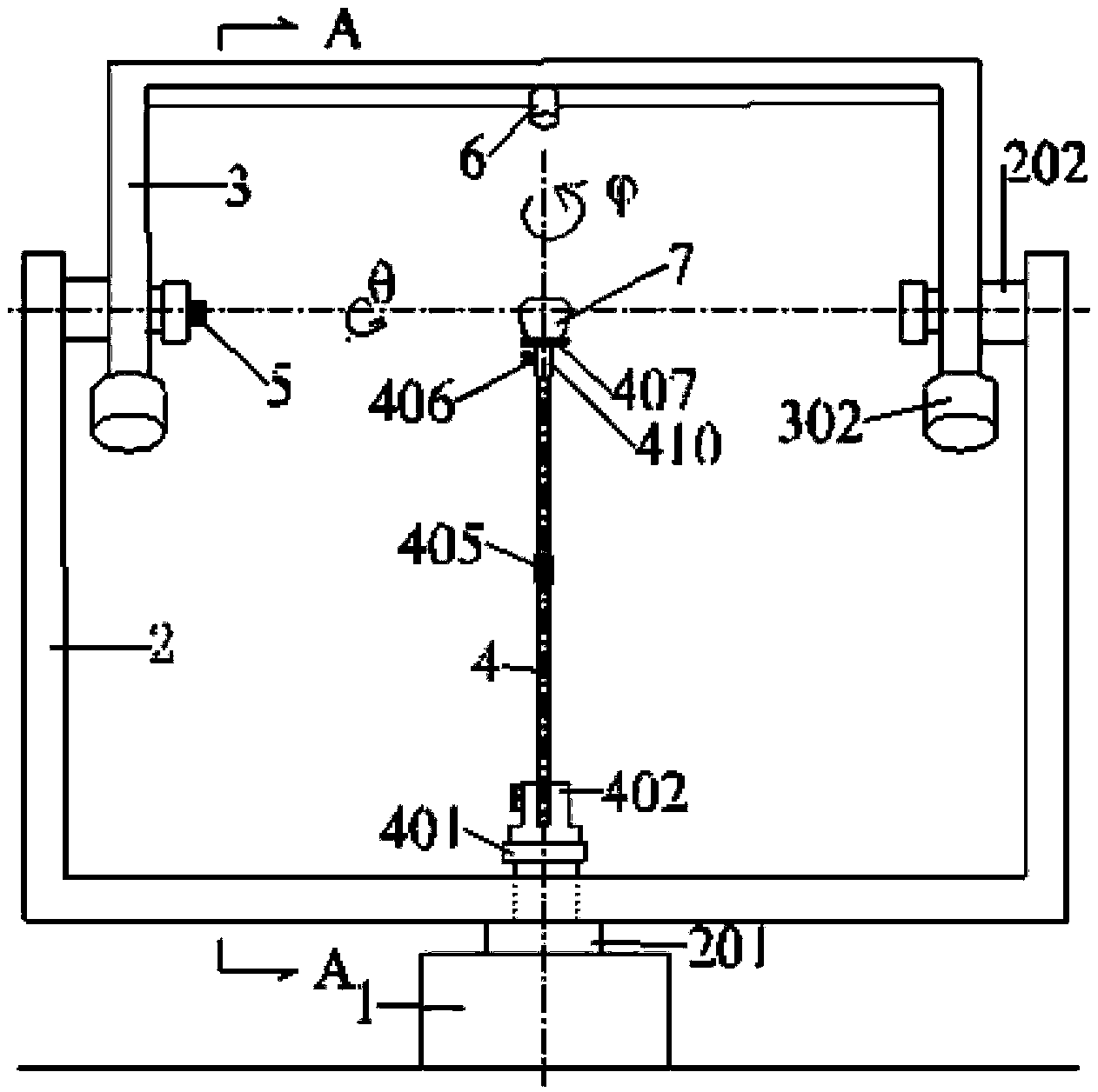
[0048] figure 1 is the front view of the full-space distribution photometric tester according to the ...


PUM


Abstract

The invention provides a fixed light source-type full space distribution luminosity measurement instrument. The luminosity measurement instrument comprises a base, a vertical rotating mechanism, a vertical U-shaped rotating arm, a horizontal rotating mechanism, a horizontal U-shaped rotating arm, a to-be-measured light source correcting bracket, a positioning laser and a light detector, wherein the vertical rotating mechanism is arranged on the base; the vertical U-shaped rotating arm consists of a beam and two arms and is fixed to the vertical rotating mechanism; the horizontal rotating mechanism is arranged inside the two arms of the vertical U-shaped rotating arm; the horizontal U-shaped rotating arm consists of a beam and two arms, and the two arms of the horizontal U-shaped rotating arm are connected with the horizontal rotating mechanism; one end of the to-be-measured light source correcting bracket is fixed in the center of the beam of the vertical U-shaped rotating arm, and the other end of the to-be-measured light source correcting bracket is suitable for holding a to-be-measured light source; the positioning laser is fixed to the horizontal U-shaped rotating arm, and the positioning laser and the horizontal rotating mechanism are in the same axis; the light detector is fixed in the center of the beam of the horizontal U-shaped rotating arm; the central lines of the light detector and the to-be-measured light source correcting bracket are in the same vertical plane. Through the adoption of the novel conception on the structure, the measurement precision can be improved effectively.

Description

technical field [0001] The invention relates to a fixed light source-type full-space distribution photometric tester, which is used for measuring the luminous flux and light intensity of various light sources and lamps such as various types of motor vehicle lamps at fixed installation positions and projecting lamps that need to be installed at fixed angles. Distribution and light color distribution for near-field full-space precision measurement. Background technique [0002] For the measurement of distributed photometry, illuminance measurement is generally used to measure the luminous flux and light intensity distribution of light sources or lamps, and a spectrometer is used to measure the light color distribution. During measurement, by measuring the illuminance distribution of the simulated spherical surface centered on the measured light source, the total luminous flux of the measured light source is calculated by numerical integration, and the light intensity of each p...

Claims


Application Information

Patent Timeline
Patent Type & Authority Applications(China)
IPC IPC(8): G01J1/00G01J1/04
Inventor 凌铭黄中荣张建文章世骏卜伟理
Owner SHANGHAI MOTOR VEHICLE INSPECTION CERTIFICATION & TECH INNOVATION CENT CO LTD
Why Eureka
Try Eureka