
Pipe Inspection System

A detection system and pipe technology, applied in measuring devices, analytical materials, material magnetic variables, etc., can solve the problems of poor radiation resistance, short service life, and easy damage of optical encoders, and achieve accurate pipe axial position detection results. , to ensure accuracy, to solve the effect of conversion problems

Active Publication Date: 2016-04-27
贵州西能电力建设有限公司 +1
View PDF7 Cites 0 Cited by
  • Summary
  • Abstract
  • Description
  • Claims
  • Application Information

AI Technical Summary

Problems solved by technology

However, optical encoders have poor radiation resistance in underwater high-radiation environments, are easily damaged, have short service life, and are not ideal in stability and reliability.

Method used


Image

  • Pipe Inspection System
  • Pipe Inspection System
  • Pipe Inspection System

Examples


Embodiment Construction

[0053] Embodiments of the present invention are described below through specific examples, and those skilled in the art can easily understand other advantages and effects of the present invention from the content disclosed in this specification. The present invention can also be implemented or applied through other different specific implementation modes, and various modifications or changes can be made to the details in this specification based on different viewpoints and applications without departing from the spirit of the present invention.

[0054] see Figure 1 to Figure 7 . It should be noted that the diagrams provided in this embodiment are only schematically illustrating the basic idea of ​​the present invention, and only the components related to the present invention are shown in the diagrams rather than the number, shape and shape of the components in actual implementation. Dimensional drawing, the type, quantity and proportion of each component can be changed arb...


PUM


Abstract

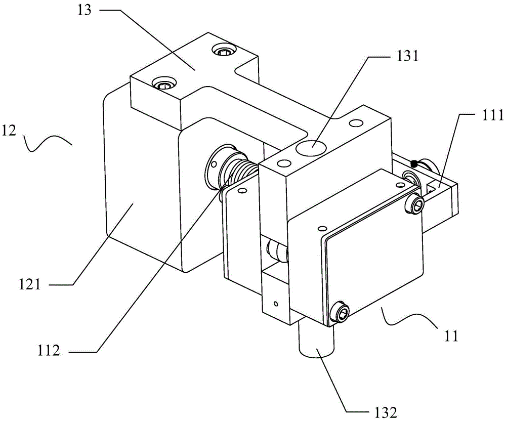
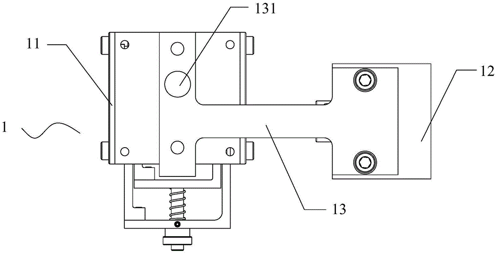
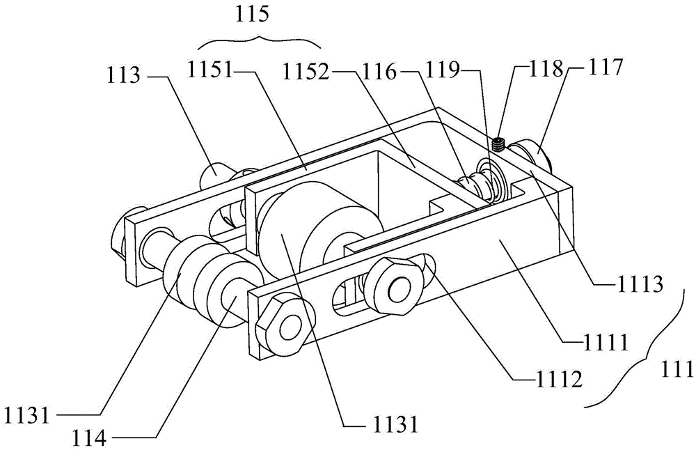
The invention provides a pipe detection system, which includes a signal acquisition device and a signal processing device; the signal acquisition device includes a transmission structure and a collection structure, and the transmission structure and the collection structure are connected and fixed by a fixed bracket; the collection structure includes a sealed cabin and a fixed The rotary transformer installed in the sealed cabin, the rotor shaft of the rotary transformer passes through the side wall of the sealed cabin; the transmission structure includes a transmission main shaft and a transmission auxiliary shaft installed in parallel on a support frame, the transmission main shaft and the transmission auxiliary shaft The distance between the shafts is adjusted by a fine-tuning assembly set on the support frame; one end of the drive shaft is connected to the rotor shaft of the resolver through a flexible coupling; the output end of the resolver is connected to the signal processing device; the fixed bracket One end is fixedly connected with the airtight cabin, and the other end is fixedly connected with the supporting frame. The pipe detection system of the invention is suitable for use in harsh environments, and can obtain accurate and reliable axial position information of the pipe.

Description

technical field [0001] The invention relates to the technical field of non-destructive testing and automatic flaw detection, in particular to a pipe material testing system. Background technique [0002] In the process of inspecting the pipe, it is necessary to locate the acquired detection signal in the axial direction. Once a defect is found on the pipe, the position of the defect in the axial direction of the pipe should be quickly determined. [0003] In the prior art, the positioning of the axial position of the pipe is obtained by transmitting the collected axial position signal to the interface of the detector through an optical encoder, and then processing and analyzing it through the detector. However, optical encoders have poor radiation resistance, are easily damaged, have short service life, and are unsatisfactory in stability and reliability in underwater high-radioactive environments. [0004] Moreover, the signal transmitted from the optical encoder to the de...

Claims


Application Information

Patent Timeline
Patent Type & Authority Patents(China)
IPC IPC(8): G01N27/90G01N27/9093
Inventor 曹强未永飞冯利法李青华叶琛
Owner 贵州西能电力建设有限公司
Learn More