A solar centralized hot water system with heat storage function

A solar collector and hot water system technology, which is applied in the field of solar concentrated hot water systems with heat storage function, can solve the problems of vacuum glass tube burst, shortened life, aging of non-metallic seals, etc., to reduce energy consumption, Effective utilization and reduction of floor space

A solar collector and hot water system technology, which is applied in the field of solar concentrated hot water systems with heat storage function, can solve the problems of vacuum glass tube burst, shortened life, aging of non-metallic seals, etc., to reduce energy consumption, Effective utilization and reduction of floor space

CN103697607BActive Publication Date: 2016-08-24RES INST OF XIAN JIAOTONG UNIV & SUZHOU

Image

  • A solar centralized hot water system with heat storage function
  • A solar centralized hot water system with heat storage function
  • A solar centralized hot water system with heat storage function

Examples


Embodiment 1

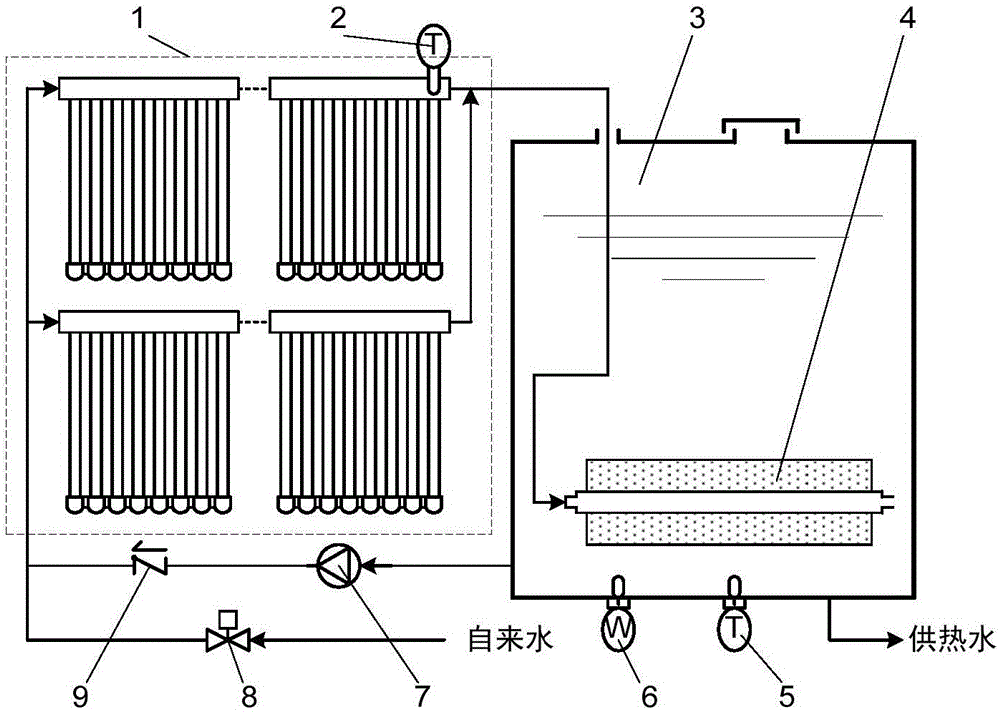
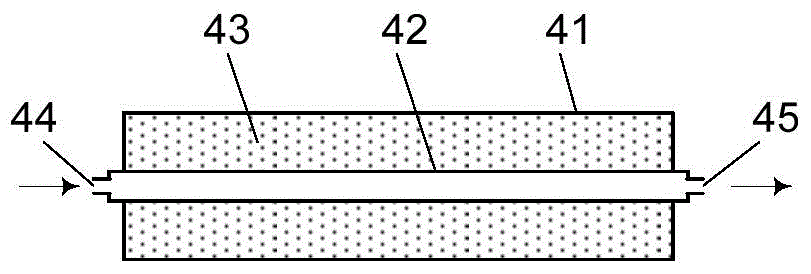
[0038] Such as figure 1 and image 3 As shown, the bottom of the water tank 3 is equipped with a heat accumulator 4, the heat accumulator 4 includes a heat accumulator shell 41 and a heat accumulator core pipe 42, and the heat accumulator shell 41 and the heat accumulator core pipe 42 form a jacket. The heat storage medium 43 is sealedly filled in the jacket, and the heat storage medium 43 is a liquid-solid phase change heat storage medium, and its phase change temperature T R Higher than the set system hot water supply temperature T S , and lower than 70°C, the phase transition temperature T of the heat storage medium 43 R =50~70°C, the preferred value is 55~60°C, the two ends of the heat accumulator core tube 42 are respectively the heat accumulator waterway inlet 44 and the heat accumulator waterway outlet 45, the heat accumulator waterway inlet 44 and the solar collector The outlet of the solar collector array 1 is connected, and the accumulator waterway outlet 45 is di...

Embodiment 2

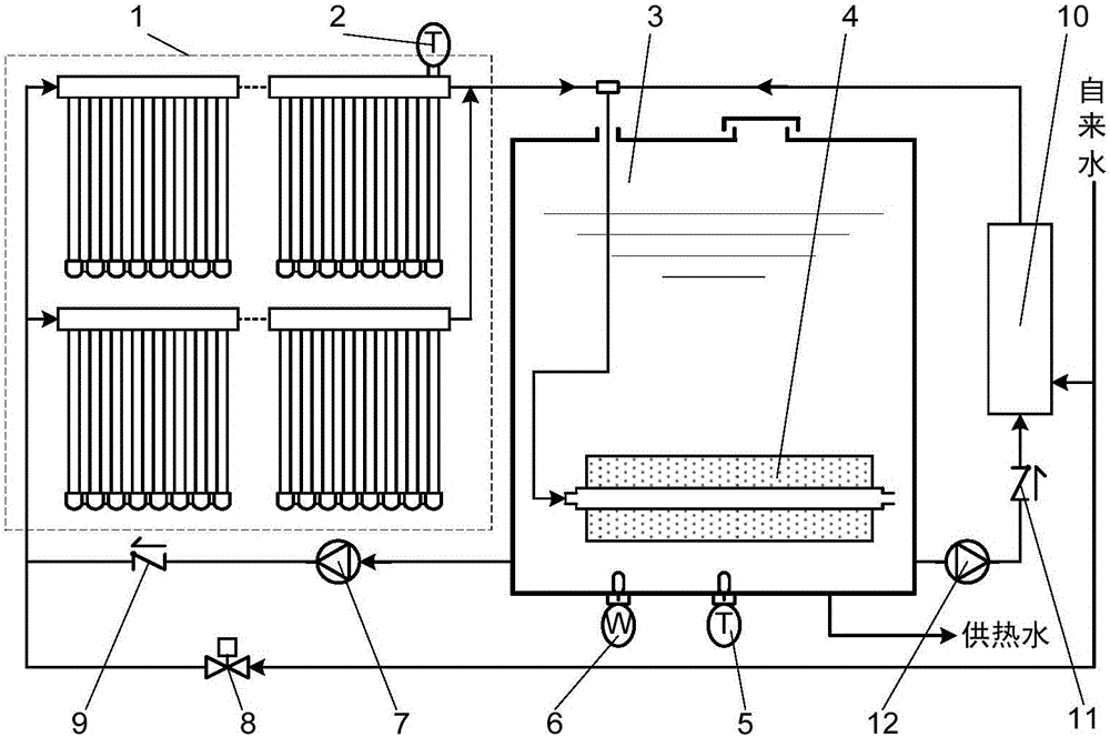
[0051] Such as figure 2 As shown, comparing this embodiment with Embodiment 1, an auxiliary heat source 10 (electric heater, heat pump, etc.) is added to the system. The lower part of the water tank 3 is connected, and the water outlet of the auxiliary heat source 10 is connected with the water inlet 44 of the accumulator; when the auxiliary heat source 10 (especially the heat pump) has the function of direct heat water production at the same time, its single direct heat water production inlet is also connected with Mains water connection. On the basis of the working method of embodiment 1, this embodiment relies on the auxiliary heat source 10 to supplement the production and supply of hot water under the condition of insufficient solar radiation and insufficient water production of the solar collector, so as to realize the all-weather hot water supply of the system; After the temperature of the water tank is reduced due to heat dissipation, the auxiliary heat source 10 als...


PUM


Abstract

The invention discloses a solar central water heating system with a heat accumulation function, which comprises a solar thermal collector array, a water tank, a collector circulating pump, a check valve, an electromagnetic valve and other parts. A heat accumulator filled with phase-change heat accumulation medium is arranged on the bottom in the water tank, and the interior of a heat accumulator core tube is a water passage. A heat accumulator water passage inlet is connected with the outlet of the solar thermal collector array, a heat accumulator outlet is directly open in the hot water storage tank, and the inlet of the solar thermal collector array is connected with the bottom of the hot water storage tank sequentially through the check valve and the collector circulating pump and connected with a tap water supply pipeline through the water-lifting electromagnetic valve. Both hot water heated by the solar thermal collectors and cold water replenished into the water tank first flow through the heat accumulator core tube and exchange heat with the heat accumulator. When the water temperature in the water tank is higher or lower than the phase change temperature of the heat accumulation medium in the heat accumulator, heat is released to the heat accumulator or heat is absorbed from the heat accumulator. By means of the heat absorption and release of the heat accumulator, energy consumption can be reduced, and solar radiation energy can be effectively utilized by the way of peak load shifting.

Description

technical field [0001] The invention relates to the field of centralized production and supply of domestic hot water by using solar energy, in particular to a solar centralized hot water system with heat storage function and its optimized working method. Background technique [0002] With the decline of traditional fossil energy such as oil, coal, and natural gas, and the increasingly serious environmental problems caused by the use of these fossil energy, the development of various clean energy and renewable energy utilization technologies has received more and more attention. Among them, the use of large-scale solar heat collectors on buildings to centrally supply domestic hot water to buildings is an effective means of utilizing renewable energy and has excellent environmental performance. With the adjustment of urban energy structure and the characteristics of urban buildings developing towards middle and high-rise buildings, the application of engineering-scale solar co...

Claims


Application Information

Patent Timeline
24 Aug 2016
Publication
CN103697607B
IPC
F24J2/34; F24J2/46
CPC
Y02E10/40
Inventors
高秀峰; 柳佳力