Edge-matching-based relative pose calibration method of laser range finder and camera

A technology of laser range finder and relative pose, which is applied in the direction of instruments, measuring devices, and photo interpretation

Active Publication Date: 2014-04-16
HANGZHOU JIAZHI TECH CO LTD
View PDF3 Cites 29 Cited by
  • Summary
  • Abstract
  • Description
  • Claims
  • Application Information

AI Technical Summary

Problems solved by technology

[0004]These methods all depend on specific objects, require special preparation, and are not conducive to online operation

Method used


Image

  • Edge-matching-based relative pose calibration method of laser range finder and camera
  • Edge-matching-based relative pose calibration method of laser range finder and camera
  • Edge-matching-based relative pose calibration method of laser range finder and camera

Examples


Embodiment Construction

[0048] According to the method for calibrating the relative pose of the laser rangefinder and the camera based on edge matching in the present invention, after calibration, the point cloud collected by the laser rangefinder can accurately correspond to the image collected by the camera. On the one hand, the image can color the point cloud to obtain a colored point cloud, or paste a colored texture on the surface mesh with the point cloud as the vertex to obtain a textured surface model; on the other hand, the point cloud can indicate the depth of a part of the image area, Provide support for applications such as image-based recognition and positioning.

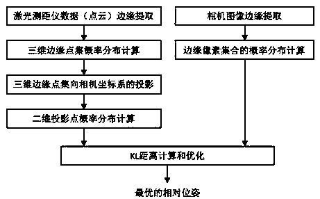
[0049]When calibrating, let the laser rangefinder and camera collect data at the same time, and ensure that most of their observation ranges overlap, process the point cloud collected by the laser rangefinder and the image collected by the camera, and get the laser rangefinder and camera online relative pose.

[0050] Such as...


PUM


Abstract

The invention discloses an edge-matching-based relative pose calibration method of a laser range finder and a camera. The relative pose calibration method comprises the steps: extracting a point cloud data edge contour of the laser range finder and an image edge contour of the camera firstly; establishing the probability distribution of a point cloud data edge, namely probability distribution of an image edge; and then minimizing a KL distance of the two distributions to obtain a relative pose parameter of the laser range finder and the camera. The relative pose calibration method is independent of a specific environment structure and auxiliary objects such as calibration boards, can run in an on-line manner and can be used for timely updating the relative pose of the laser range finder and the camera; with the adoption of the relative pose calibration method, the extracted point cloud data edge contour and the image edge contour can be further used for other applications such as environment object identification and location.

Description

technical field [0001] The invention relates to the field of multi-sensor information fusion, in particular to a method for calibrating the relative pose of a laser rangefinder and a camera based on edge matching. Background technique: [0002] The traditional laser rangefinder and camera relative pose calibration method is generally implemented by a calibration board. By visually identifying the corners of the calibration board, the constraints that these corners are located in the plane of the calibration board in space are established, and the error function is minimized to obtain a representation of the relative position. rotation and translation matrices . [0003] Other methods do not require a calibration plate, but also require a specific structure of the environment to establish geometric constraints. [0004] These methods all rely on specific objects, require special preparation, and are not conducive to online operation. Based on this, the present invention ...

Claims


Application Information

Patent Timeline
Patent Type & Authority Applications(China)
IPC IPC(8): G01C11/04G01B11/00
CPCG01C11/04
Inventor 熊蓉李千山
Owner HANGZHOU JIAZHI TECH CO LTD
Why Eureka
Try Eureka