
Three pin positioning structure positioning plate

A technology of positioning structure and positioning plate, applied in the direction of positioning device, clamping, support, etc., to achieve the effect of ensuring positioning accuracy and stability

Inactive Publication Date: 2014-04-30
LIUZHOU YONGXIN MACHINERY PARTS MFG
View PDF6 Cites 2 Cited by
  • Summary
  • Abstract
  • Description
  • Claims
  • Application Information

AI Technical Summary

Problems solved by technology

[0003] The purpose of the present invention is to provide a positioning plate with a three-needle positioning structure to solve the stability and accuracy problems of ejector pin positioning

Method used


Image

  • Three pin positioning structure positioning plate

Examples


Embodiment Construction

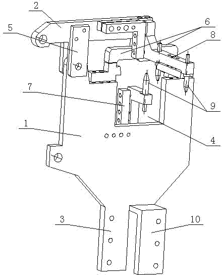
[0010] Such as figure 1 As shown, the positioning plate of the three-needle positioning structure described in the embodiment of the present invention includes an overturning beam 2 and a positioning plate 1, and the left side of the bottom of the positioning plate 1 is a straight connecting plate 3 integrally formed with the positioning plate 1. The right side of the bottom of the positioning plate 1 is provided with an L-shaped connecting plate 10, the L-shaped connecting plate 10 is integrally formed with the positioning plate 1, the top of the positioning plate 1 is provided with a notch 4, and the right side of the flip beam 2 The support plate 5 is hinged with the positioning plate 1, the overturn beam 2 is fixedly connected with the support plate 5, the left side of the overturn beam 2 is connected with the center of a door-shaped seat 6, and the door-shaped seat 6 is docked with the notch 4 of the positioning plate; the inside of the notch is provided with a first thim...


PUM


Abstract

A three pin positioning structure positioning plate comprises a flipping beam and a positioning plate, the top of the positioning plate is provided with a recess, the right side of the flipping beam is hinged to the positioning plate through a support plate which is fixedly connected with the flipping beam, and the left side of the flipping beam is connected with the center of a gate-shaped seat which is in butt joint with the recess of the positioning plate; the inside of the recess is provided with a first ejection pin fixing member, and an ejection pin is upwardly mounted on the top portion of the first ejection pin fixing member; the outside of the flipping beam is provided with a second ejection pin fixing member, and two ejection pins are downwardly mounted on the lower portion of the second ejection pin fixing member. The three pin positioning structure positioning plate can achieve linear positioning of a workpiece and fix the workpiece through the flipping beam driving the gate-shaped seat to match with the positioning plate, thereby ensuring positioning accuracy and stability.

Description

technical field [0001] The invention relates to a positioning plate with a three-needle positioning structure, which belongs to the field of processing and positioning of mechanical accessories. Background technique [0002] There are many kinds of machining equipment at present, among which various auxiliary equipment are needed in the process of positioning, thimble is one of them, and thimble often plays the role of support. However, the thimble cannot be positioned directly during use, and must be positioned with the help of tools such as a positioning plate, so the structure of the positioning plate also determines the stability and accuracy of the positioning of the thimble. Contents of the invention [0003] The purpose of the present invention is to provide a positioning plate with a three-needle positioning structure to solve the problems of stability and precision of ejector pin positioning. [0004] The purpose of the present invention is specifically achieved ...

Claims


Application Information

Patent Timeline
Patent Type & Authority Applications(China)
IPC IPC(8): B25B11/00
CPCB23Q3/18
Inventor 刘浩
Owner LIUZHOU YONGXIN MACHINERY PARTS MFG
Learn More