Check patentability & draft patents in minutes with Patsnap Eureka AI!

photon counting detector

A technology of photon counting and detector array, which is applied in the direction of instruments, measuring devices, scientific instruments, etc., and can solve problems such as signal distortion

Active Publication Date: 2016-06-29
KONINKLJIJKE PHILIPS NV
View PDF9 Cites 0 Cited by
  • Summary
  • Abstract
  • Description
  • Claims
  • Application Information

AI Technical Summary

Problems solved by technology

Also, photons scattered in a non-sensitive detector volume close to the sensitive detector volume can enter the sensitive detector volume, distorting the measured signal

Method used


Image

  • photon counting detector
  • photon counting detector
  • photon counting detector

Examples


Embodiment Construction

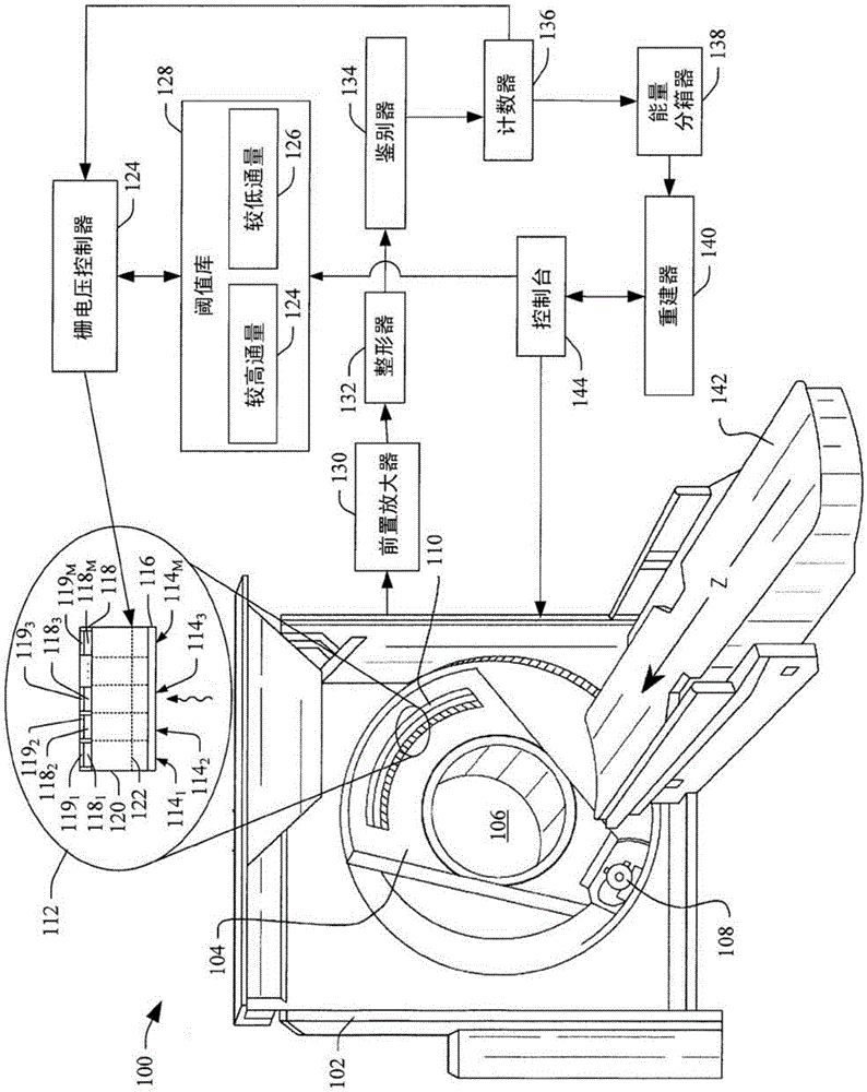
[0023] figure 1 An imaging system 100, such as a computed tomography (CT) scanner, is schematically illustrated. The imaging system 100 includes a fixed frame 102 and a rotating frame 104, and the rotating frame 104 is rotatably supported by the fixed frame 102. The rotating gantry 104 rotates about the inspection area 106 about the longitudinal axis or z-axis. The imaging system 100 also includes a radiation source 108, such as an X-ray tube, which is supported by a rotating gantry 104 and rotates with the rotating gantry 104 about the longitudinal axis or z-axis around the inspection area 106. The radiation source 108 emits multi-energy ionizing radiation collimated by a collimator to generate a generally fan-shaped, wedge-shaped, or cone-shaped radiation beam that penetrates the inspection area 106.

[0024] The imaging system 100 further includes a detector array 110 whose subtend is an angular arc opposite to the radiation source 106 at the inspection area 108. The illust...


PUM


Abstract

A detector array includes at least one direct conversion detector pixel (114-114M) configured to detect photons of polychromatic ionizing radiation. The pixel includes a cathode layer (116), an anode layer (118), a direct conversion material (120), and a gate electrode, the anode layer including an anode electrode (118- 118M), the direct conversion material is placed between the cathode layer and the anode layer, and the gate electrode is placed in the direct conversion material parallel to and between the cathode layer and the anode layer.

Description

Technical field [0001] The following generally relates to a direct conversion photon counting detector, and is described through the specific application of computer tomography (CT); however, the following is also applicable to other imaging modalities. Background technique [0002] A computer tomography (CT) scanner includes a rotating gantry that is rotatably mounted to a fixed gantry. The rotating frame supports the X-ray tube. The detector array is located opposite the X-ray tube passing through the inspection area. The rotating gantry and the X-ray tube rotate about the longitudinal axis or z-axis around the inspection area. The X-ray tube is configured to emit multi-energy ionizing radiation that penetrates the inspection area and irradiates the detector array. The detector array includes a one-dimensional or two-dimensional array of detector pixels that detect radiation and generate signals indicative of the radiation. Each pixel is associated with a readout channel, w...

Claims


Application Information

Patent Timeline
Patent Type & Authority Patents(China)
IPC IPC(8): G01T1/24
CPCG01T1/241G01T1/247G01T1/24
Inventor E·勒斯尔R·普罗克绍
Owner KONINKLJIJKE PHILIPS NV
Features
  • R&D
  • Intellectual Property
  • Life Sciences
  • Materials
  • Tech Scout
  • Unparalleled Data Quality
  • Higher Quality Content
  • 60% Fewer Hallucinations
Learn More