Direct conversion photon counting detector

a detector and photon technology, applied in the direction of instruments, x/gamma/cosmic radiation measurement, radiation control devices, etc., can solve the problems of limiting the performance of steering electrode configuration, electrical field distortion, and limit the pixel area of electrodes,

Active Publication Date: 2015-08-20
KONINKLJIJKE PHILIPS NV
View PDF2 Cites 15 Cited by
  • Summary
  • Abstract
  • Description
  • Claims
  • Application Information

AI Technical Summary

Benefits of technology

[0007]Embodiments according to the present invention are directed to a direct conversion photon counting detector, comprising a detector cathode, a detector anode and a direct conversion material layer. The direct conversion material layer is positioned between said detector cathode and said detector anode. The detector anode and / or detector cathode comprise a plurality of electrode pixels that are adapted to detect a presence of electrons or holes. At least one of the electrode pixels is segmented into at least a first electrode pixel segment, a second electrode pixel segment and a third electrode pixel segment. An electrical potential of the third electrode pixel segment is at a more electrically repellant value than an electrical potential of the first electrode pixel segment and than an electrical potential of the second electrode pixel segment. The detector further comprises electronic circuitry electrically coupled to the first electrode segment and to the second electrode segment to generate a first electrical signal and a second electrical signal respectively. The electronic circuitry comprises a signal subtractor configured to subtract the second electrical signal from the first electrical signal.

Problems solved by technology

However, there are limitations to reducing electrode pixel area, most importantly because of cross-talk between adjacent electrode pixels due to charge sharing.
It is inherent to these configurations that charges are trapped near the collecting electrode which polarizes the detector, causing the electrical field to become distorted.
This effect is especially limiting performance of the steering electrode configuration.
However, there needs to be a relatively large potential difference (at least several tens of volts) between the closely neighboring collecting and non-collecting electrodes to ensure good operation, coplanar grids are technically quite challenging to design, manufacture and operate and compromises must be made to overcome the potential difference between the collecting and non-collecting electrodes while subtracting the signals.

Method used


Image

  • Direct conversion photon counting detector
  • Direct conversion photon counting detector
  • Direct conversion photon counting detector

Examples


Embodiment Construction

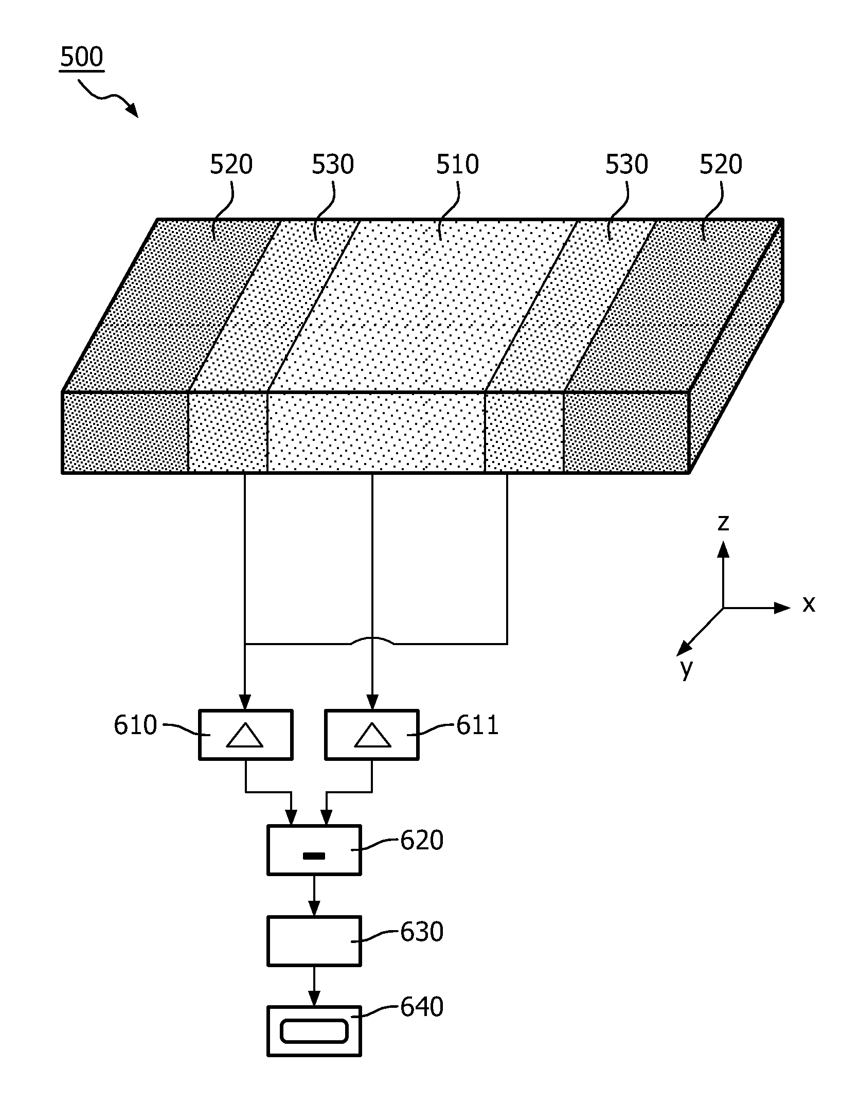
[0022]A direct conversion photon counting detector, an imaging system and a method to detect photons with a direct conversion photon counting detector are disclosed.

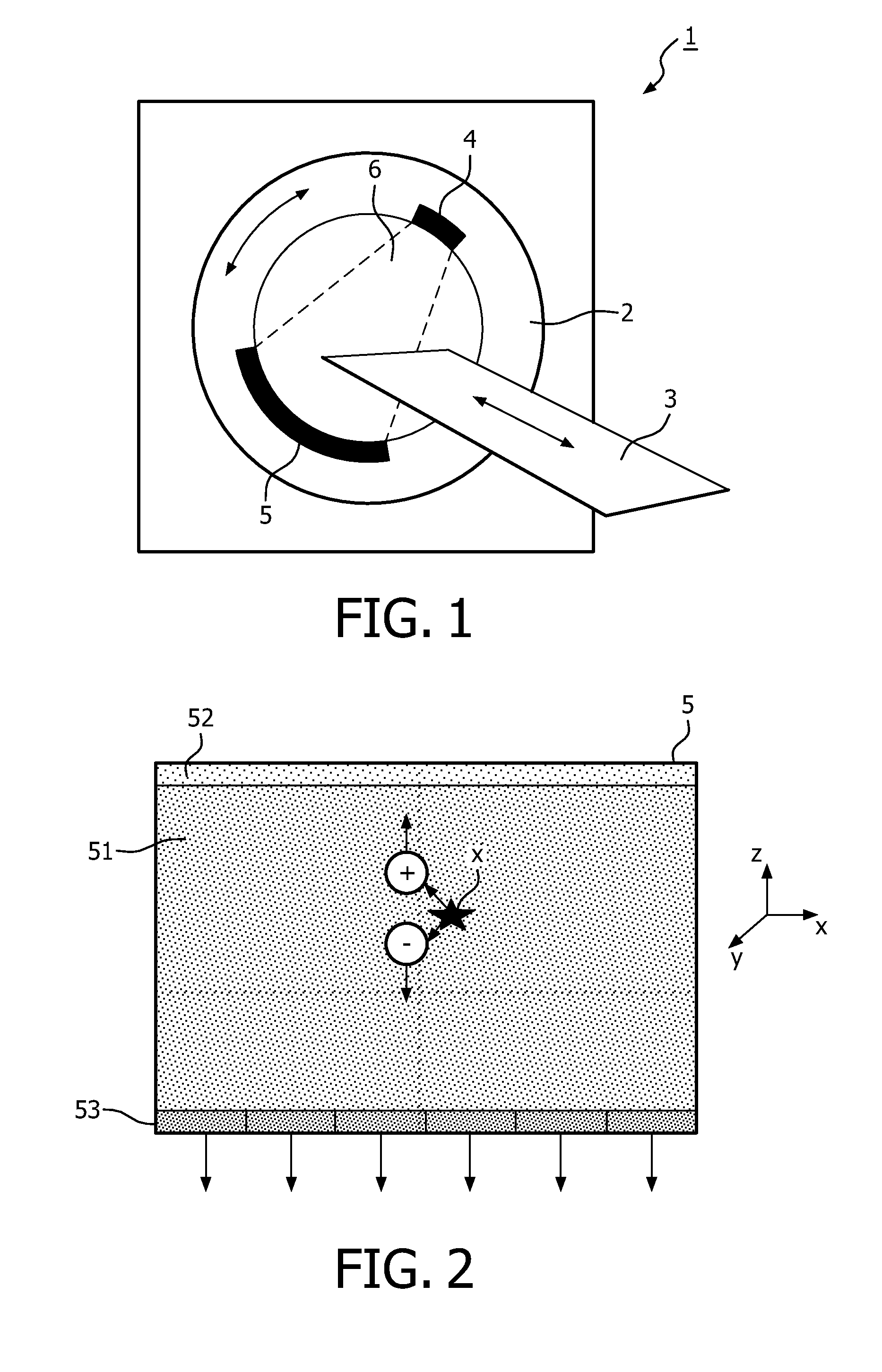
[0023]Direct conversion photon counting detection is a technique that is predominantly used in astrophysics, medical imaging and non-medical imaging such as luggage scanning. Embodiments of the present invention are described and illustrated relating to medical imaging, in particular to x-ray radiation detection in computed tomography, but a skilled person would understand how to adapt the described embodiments for other types of imaging, including how to adapt the direct conversion photon counting detector for detecting photons with other energy levels (such as gamma-ray radiation).

[0024]The embodiments and examples described below are described for the case that electron collection is used. The present invention also covers the case of hole collection. To achieve this, a skilled person would understand that the same em...


PUM


Abstract

The present invention discloses a pixilated direct conversion photon counting detector with a direct conversion material layer and a pixilated electrode. Individual electrode pixels are segmented into three segments (510, 520, 530), wherein one of the segments (520) is operated at a more electrically repellant value than that of the other two (510, 530). Said other two segments are connected to electric circuitry (610, 611, 620, 630) that is arranged to generate signals which are indicative of a count of electrons or holes that approach each of the respective electrode pixel segments and to subtract the generated signals from each other.

Description

BACKGROUND OF THE INVENTION[0001]The present invention generally relates to a direct conversion photon counting detector, an imaging system and a method to detect photons with a direct conversion photon counting detector.[0002]Direct conversion photon counting detectors are well-known in the art for single photon detection in for instance astrophysics or medical imaging, such as computed tomography (CT), positron emission tomography (PET), single photon emission computed tomography (SPECT) and the like. A direct conversion photon counting detector is disclosed in J.D. Eskin et.al, Journal of Applied Physics, volume 85, Number 2, page 647-659, 15 January 1999.[0003]A bulk of a direct conversion photon counting detector is composed of a layer of a direct conversion material, usually a single-crystal semi-conductor. Inbound radiation (such as x-rays, y-rays) is absorbed by the direct conversion material and, due to a photo-electric interaction, mobile electron-hole pairs are generated ...

Claims


Application Information

Patent Timeline
Patent Type & Authority Applications(United States)
IPC IPC(8): G01T1/24
CPCG01T1/249G01T1/241
Inventor ENGEL, KLAUS JUERGENSTEADMAN BOOKER, ROGERHERRMANN, CHRISTOPH
Owner KONINKLJIJKE PHILIPS NV
Why Eureka
Try Eureka