Horizontal-drainage type double-layer drainage and downspout device and installation method for same

An installation method and double-layer technology, which can be used in roof drainage, building material processing, construction, etc., can solve the problems of poor aesthetics, and achieve the effect of reasonable arrangement, convenient construction and strong practicability

Active Publication Date: 2014-05-07
CHINA RAILWAY CONSTR ENG GROUP +1
View PDF7 Cites 2 Cited by
  • Summary
  • Abstract
  • Description
  • Claims
  • Application Information

AI Technical Summary

Problems solved by technology

Although the design of this kind of drain can realize the function of removing rainwater above the surface layer and water vapor in the insulation layer, slope-finding layer, etc., but the aesthetics is poor, and the steep slope has hidden dangers in use, and the rainwater above the surface layer will flow back through the drain. In the roof structure layer such as insulation layer and slope layer

Method used


Image

  • Horizontal-drainage type double-layer drainage and downspout device and installation method for same
  • Horizontal-drainage type double-layer drainage and downspout device and installation method for same
  • Horizontal-drainage type double-layer drainage and downspout device and installation method for same

Examples


Embodiment Construction

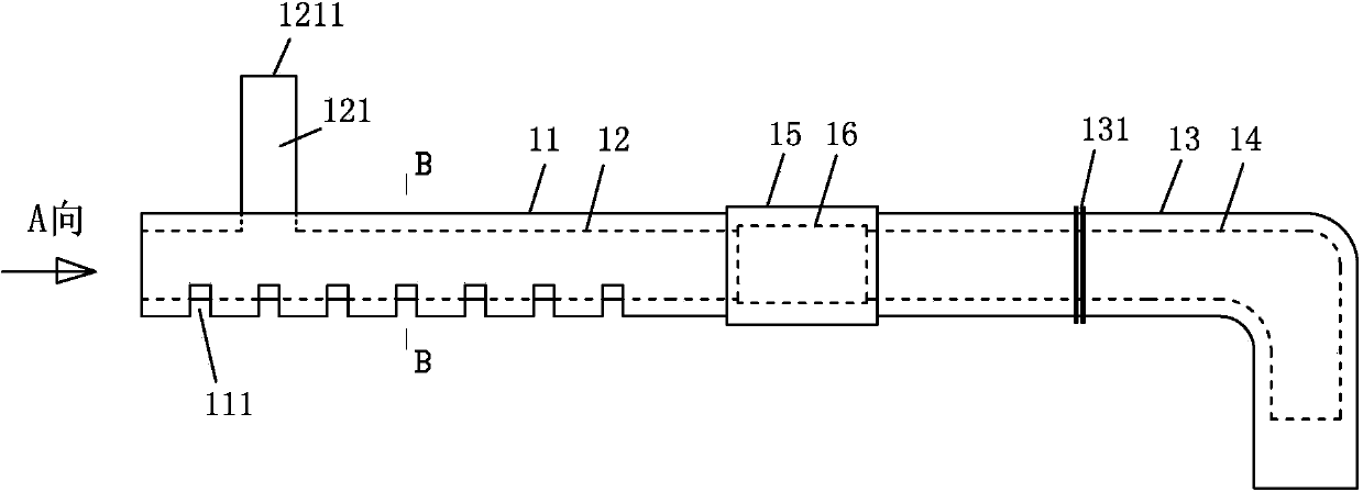
[0030] like Figure 1 to Figure 3 As shown, the horizontal row type double-deck drainage device of the present invention comprises a straight section double-layer pipe and a bent section double-layer pipe, wherein:

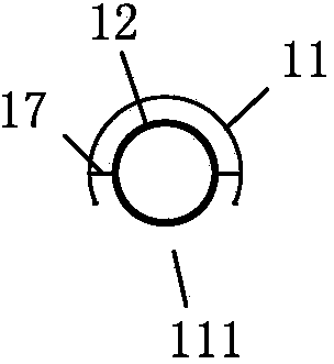
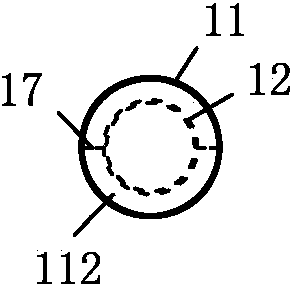
[0031] The straight double-layer pipe includes an outer drain straight pipe 11 with one end open and the other end closed, and an inner drain straight pipe 12 with one end open and the other end closed. The bottom of the outer drain straight pipe 11 is provided with a row of drainage hole 111, the inner straight drainage pipe 12 is placed in the outer straight drainage pipe 11 and the vertical drainage pipe 121 vertically arranged on the inner straight drainage pipe 12 runs from the opening on the top of the outer straight drainage pipe 11 ( not marked in the figure), the water inlet 1211 of the vertical drain pipe 121 is used to cover the drain cover 20;

[0032] The double-layered tube of the curved section includes an outer elbow 13 with both ends open (referr...


PUM


Abstract

The invention discloses a horizontal-drainage type double-layer drainage and downspout device and an installation method for the same. The device comprises straight-section double-layer tubes and bent-section double-layer tubes, wherein the straight-section double-layer tubes comprise an inner-layer drainage straight tube and an outer-layer drainage straight tube, a drainage hole is formed in the bottom of the outer-layer drainage straight tube, and the inner-layer drainage straight tube is arranged in the outer-layer drainage straight tube and a vertical drainage tube on the inner-layer drainage straight tube stretches out from the top of the outer-layer drainage straight tube; the bent-section double-layer tubes comprise an outer-layer bent tube, an inner-layer bent tube is arranged in the outer-layer bent tube, and the outer wall of the outer-layer bent tube is provided with an embedding groove; the inner-layer drainage straight tube and the outer-layer drainage straight tube are connected with the inner-layer bent tube and the outer-layer bent tube. The installation method comprises the following steps of: constructing a waterproof layer; embedding rubber strips, and installing the bent-section double-layer tubes at the hole of a roof parapet wall; placing the straight-section double-layer tubes on the waterproof layer, and connecting the inner-layer drainage straight tube and the outer-layer drainage straight tube with the inner-layer bent tube and the outer-layer bent tube; constructing roof structural layers such as a heat insulation layer, reserving a groove and a tongue on a top layer, and covering a downspout cover; installing a drainage pipeline. The device disclosed by the invention is provided with the double drainage functions of top layer drainage and roof structural layer vapour elimination, and is capable of preventing rainwater on the top layer from flowing back into the roof structural layers.

Description

technical field [0001] The invention relates to a horizontal row type double-layer drainage device and an installation method thereof, and belongs to the field of manufacturing and installation of the water device (drain). Background technique [0002] The falling water device is also called the falling water outlet, which is a device that collects and guides roof rainwater into the drain pipe in the organized roof drainage method. [0003] At present, most construction units make the top surface of the downfall flush with the waterproof layer on the cement mortar leveling layer, and then use a downpipe to connect the downhole so that the top surface is at the same height as the roof surface, and the upper opening is covered with a A drain cover. The design of this kind of drain is relatively simple, and the construction is convenient, but it cannot eliminate the water vapor in the roof structure layer such as the insulation layer above the waterproof layer and the slope la...

Claims


Application Information

Patent Timeline
Patent Type & Authority Applications(China)
IPC IPC(8): E04D13/08E04D13/04E04G21/00
Inventor 王福全杨春林吴金伟
Owner CHINA RAILWAY CONSTR ENG GROUP
Why Eureka
Try Eureka