Shaft heat loss determining method

A technology for determining methods and heat loss, applied in earthwork drilling, wellbore/well components, production fluids, etc., can solve problems such as non-convergence of iterations, inability to continue iterative calculations, and inconformity with natural laws

Active Publication Date: 2014-05-07
PETROCHINA CO LTD
View PDF6 Cites 28 Cited by
  • Summary
  • Abstract
  • Description
  • Claims
  • Application Information

AI Technical Summary

Problems solved by technology

However, the above calculation method continues to calculate the entire depth of the wellbore as a whole, without considering that with the different depths of the wellbore, factors such as steam temperature in the wellbore will change, and the heat loss of the wellbore will also change accordingly. Therefore, the above method The calculation result is

Method used


Image

  • Shaft heat loss determining method
  • Shaft heat loss determining method
  • Shaft heat loss determining method

Examples


Embodiment Construction

[0082] In order to enable those skilled in the art to better understand the technical solutions in the present application, the technical solutions in the embodiments of the present application will be clearly and completely described below in conjunction with the drawings in the embodiments of the present application. Obviously, the described The embodiments are only some of the embodiments of the present application, but not all of them. Based on the embodiments in this application, all other embodiments obtained by persons of ordinary skill in the art without creative efforts shall fall within the protection scope of the present invention.

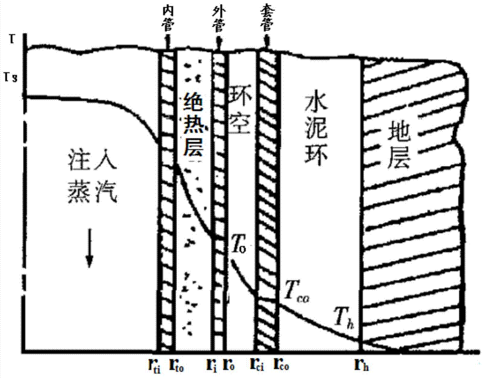
[0083] figure 1 It is a schematic diagram of the cross-sectional structure of the steam injection wellbore. like figure 1 As shown, from the center of the wellbore along the radial direction outwards are the inner pipe, the insulation layer, the outer pipe, the annular layer, the casing, the cement sheath, and the formation. After th...


PUM


Abstract

The invention provides a shaft heat loss determining method. The shaft heat loss determining method comprises the steps that calculating parameters are read in; thermal resistance values at all positions in the radius directions in a shaft and a radial upper heat loss limit value of a shaft unit are calculated; a radial initial heat loss value of the shaft unit is set; a first current value and a second current value are set; a current total thermal resistance value and a third current value are calculated in a circulatory mode, and the first current value and the second current value are updated until the updated second current value is larger than or equal to the depth of the shaft; the obtained third values are summed, and the result obtained after summation is determined to be the shaft heat loss value. By the adoption of the shaft heat loss determining method, heat loss calculation is conducted on the shaft in a sectional mode, so that the shaft heat loss result worked out is more accurate.

Description

technical field [0001] The invention relates to the field of steam injection oil recovery, in particular to a method for determining heat loss of a wellbore. Background technique [0002] In the oil extraction technology, the unprocessed oil extracted directly from the oil well is crude oil, and the viscosity of different types of crude oil is generally different. Among them, heavy oil refers to crude oil with high asphaltene and colloid content and high viscosity. Practice shows that the viscosity of heavy oil generally changes significantly with the change of temperature. As the temperature rises, the viscosity of heavy oil generally decreases, so the exploitation and transportation of super heavy oil generally requires the use of thermal means to reduce the viscosity of super heavy oil, such as the use of steam injection recovery technology for the production of super heavy oil. At present, the main method of heavy oil production is steam injection, including steam huff...

Claims


Application Information

Patent Timeline
IPC IPC(8): E21B47/00E21B43/24
Inventor 马振齐海鹰彭松良曲绍刚刘洪芹张成博宋阳钟满发郝玲
Owner PETROCHINA CO LTD
Why Eureka
Try Eureka