

Dimming circuit compatible with silicon controlled rectifier dimmer and control method
A dimming circuit and dimmer technology, applied in the direction of lamp circuit layout, light source, electric light source, etc., can solve problems such as large leakage current, flicker, affecting the working status of thyristor and LED power supply, and achieve the goal of solving the problem of flicker Effect
- Summary
- Abstract
- Description
- Claims
- Application Information
AI Technical Summary
Problems solved by technology
Method used
Image

Examples
Embodiment Construction
[0038] The present invention is described in further detail now in conjunction with accompanying drawing.
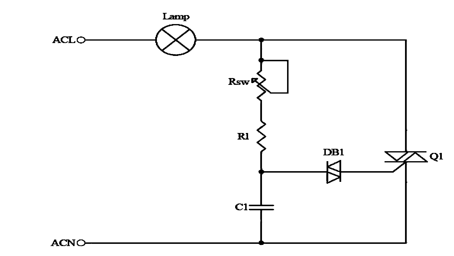
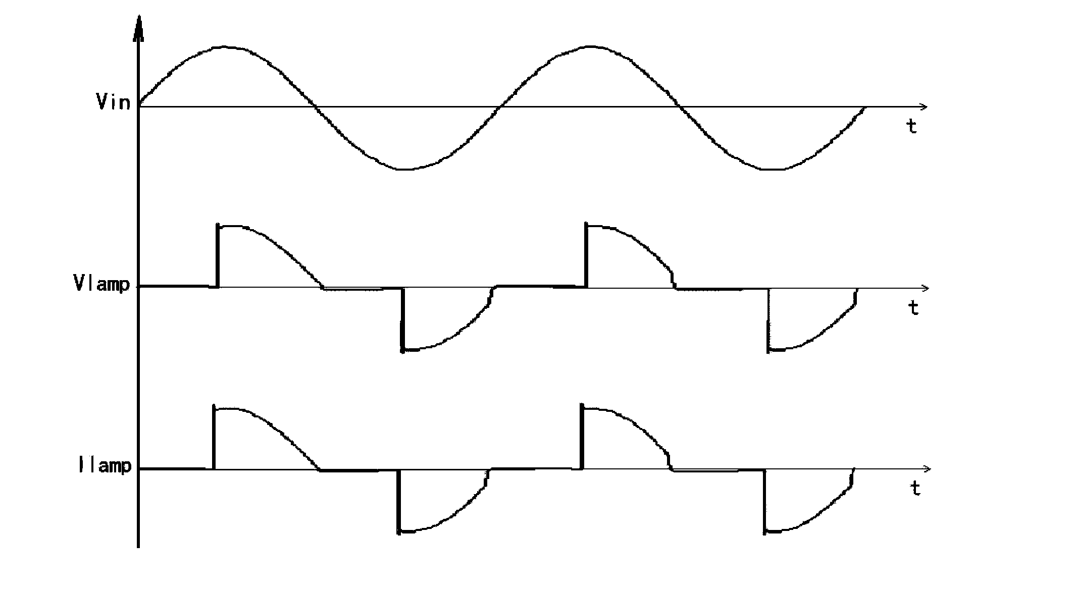
[0039] figure 1 SCR dimming schematic diagram for a traditional incandescent lamp. Among them, Lamp is an incandescent lamp, Q1 is a bidirectional thyristor, DB1 is a bidirectional trigger tube, Rsw is a variable resistor connected in series with R1, and then charges C1 to generate a variable time constant, thereby controlling the bidirectional thyristor. Opening time. This allows experimenting with dimming incandescent lamps. Such as figure 2 The waveforms at each point of phase cut at 90 degrees are shown.
[0040] However, if the LED constant current source is directly connected to the thyristor dimmer, there will be problems in its dimming. For example: Since the LED power supply is a constant current source, and the thyristor dimmer can only cut the phase of the input voltage, it can be equivalent to changing the average value of the input voltage, and changin...
PUM
 Abstract
Description
Claims
Application Information