Synchronous signal tracing method and system

A technology of synchronization signal and field synchronization, applied in the direction of cathode ray tube indicators, instruments, static indicators, etc., can solve the problem of flickering of display components, and achieve the effect of convenient debugging, solving flickering problems, and eliminating flickering problems.

Active Publication Date: 2009-08-05
ARKMICRO TECH
View PDF0 Cites 9 Cited by
  • Summary
  • Abstract
  • Description
  • Claims
  • Application Information

AI Technical Summary

Problems solved by technology

[0006] The technical problem to be solved by the present invention is to provide a synchronization signal tracking method and system, thereby solving the problem of flickering of display components when the line and field synchronization signals are unstable or abrupt when the system cannot use a large storage unit

Method used


Image

  • Synchronous signal tracing method and system
  • Synchronous signal tracing method and system
  • Synchronous signal tracing method and system

Examples


Embodiment Construction

[0037] The specific implementation manners of the present invention will be described in detail below in conjunction with the accompanying drawings.

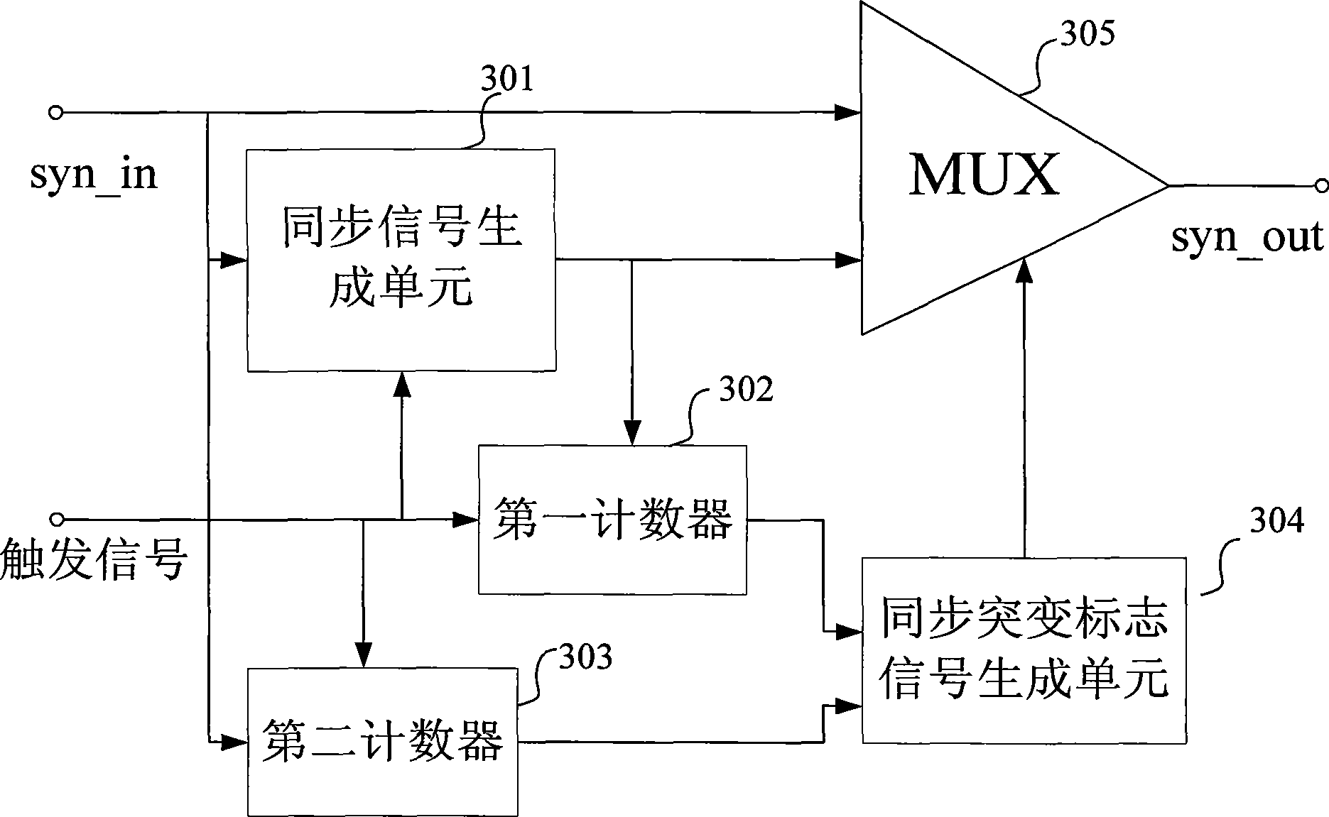
[0038] Such as image 3 Shown is a block diagram of the overall structure of the line synchronization tracking system in a synchronization signal tracking system of the present invention, the system includes a synchronization generation unit 301, a first counter 302, a second counter 303, a synchronization mutation flag signal generation unit 304 and a selection device (MUX) 305 . The input synchronous signal syn_in is input to the synchronous generating unit 301 to obtain a new synchronous signal, and the new synchronous signal and the input synchronous signal syn_in are input into the selector (MUX) 305 to select the synchronous signal syn_out that is output as the synchronous of the video display system signal, wherein the selection signal of the selector (MUX) 305 is the flag signal obtained by the synchronous mutation flag...


PUM


Abstract

The invention discloses a synchronizing signal tracking method and a system. The system comprises a synchronous generating unit, a first counter, a second counter, a synchronous mutation mark generating unit and a selector. An input synchronizing signal is input to the synchronous generating unit to obtain a new synchronizing signal, which is input to the selector together with the input synchronizing signal to obtain an output synchronizing signal as a synchronizing signal of a video display system; wherein, a selection signal of the selector is a mark signal obtained by a synchronous mutation mark signal generating unit in virtue of the first counter and the second counter; the second counter counts the input synchronizing signals by a trigger signal; and the first counter counts newly generated synchronizing signals by a trigger signal. The system can track an unstable synchronizing signal and generate a stable line-field synchronizing signal to be input to a display circuit with the unstable synchronizing signal as the standard, thus solving the scintillation problem of a display caused by unstable line-field synchronization.

Description

technical field [0001] The invention relates to an image display technology, in particular to a method and system for tracking a synchronous signal when a video image is displayed. Background technique [0002] The display of video images includes various methods such as cathode ray tube display (CRT) and liquid crystal display. Taking CRT as an example, the principle of light emission is that the electron beam emitted by the cathode of the electron gun inside the picture tube becomes small after intensity control, focusing and acceleration. The current of electrons deviates from the correct target through the action of the deflection coil, passes through the small hole or fence of the shadow mask, and bombards the phosphor on the phosphor screen, so that the phosphor is activated and emits light. R, G, and B three-color fluorescent points are lit by electron currents with different proportional intensities, and various colors will be produced. If the line deflection coil i...

Claims


Application Information

Patent Timeline
IPC IPC(8): G09G5/00G09G5/18
Inventor 严卫健刘俊秀林晓伟石岭
Owner ARKMICRO TECH
Why Eureka
Try Eureka