Metering spray valve
A technology of spray valve and quantitative valve, which is applied in the direction of lift valve, valve device, liquid distribution, etc., can solve the problem of cumbersome methods that cannot realize quantitative spray, gas filling and liquid filling.
- Summary
- Abstract
- Description
- Claims
- Application Information
AI Technical Summary
Problems solved by technology
Method used
Image
Examples
Embodiment 1
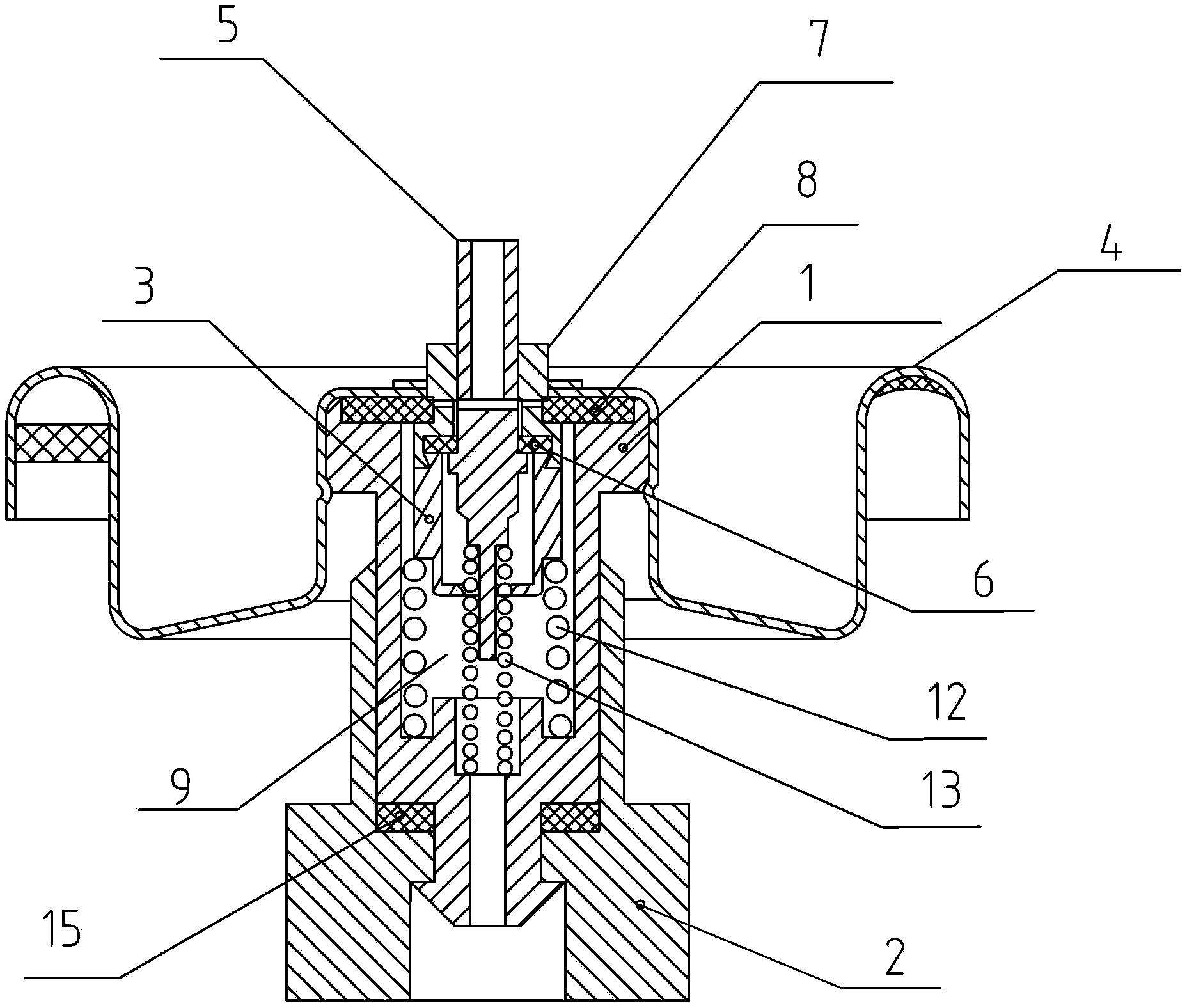
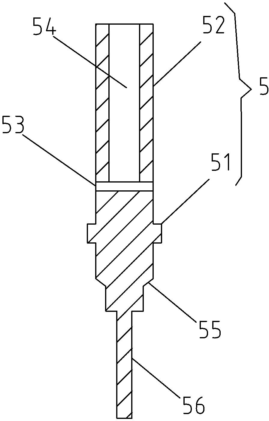
[0028] Such as figure 1 , the quantitative spray valve of this embodiment includes: an inner valve body 1, a quantitative valve chamber 3 arranged in the inner valve body 1, a sealing cover 4 sealingly fitted on the top of the quantitative valve chamber 3, and an axially penetrating sealing cover. 4 and the inner valve stem 5 of the quantitative valve chamber 3; the middle part of the inner valve stem 5 is provided with an annular boss 51, and a first sealing ring 6 is arranged between the quantitative valve chamber 3 and the sealing cover 4, and the first sealing ring 6 Seal fit with the upper rod body 52 above the annular boss 51 of the inner valve rod 5; the upper rod body 52 is provided with radially distributed liquid inlet holes 53 and axially distributed liquid discharge holes 54; The bottom of the liquid hole 54 communicates with the liquid inlet 53; the lower rod body of the inner valve rod 5 below the annular boss 51 is provided with a first annular cone surface 55, ...
Embodiment 2
[0035] On the basis of Embodiment 1, the quantitative spray valve of this embodiment has the following deformations:
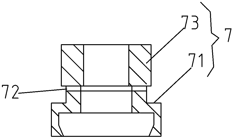
[0036] See Figures 1 to 7 , in order to achieve the purpose of filling the soft bag through the inner valve stem, the quantitative spray valve provided in this embodiment also includes: an outer valve stem 7; the bottom of the outer valve stem 7 passes through the first sealing ring 6 and the The top of the quantitative valve chamber 3 is sealed and fit, the middle part of the outer valve stem 7 has an annular platform 71, and the second sealing ring 8 is passed between the rod body 73 above the annular platform 71 and the sealing cover 4 of the outer valve stem 7 sealing fit; the rod body 73 of the outer valve stem 7 above the annular platform 71 is provided with a radial through hole 72, and the two ends of the radial through hole 72 are in sealing fit with the inner ring of the second sealing ring 8 A first spring 12 is provided between the bottom of the ...
Embodiment 3
[0040] On the basis of Embodiment 2, the quantitative spray valve of this embodiment has the following deformations:
[0041] See Figures 9 to 10 , the inner wall of the lower end of the outer valve body 2 is provided with a sleeve 21, the lower end of the inner valve body 2 is a tubular part 1-2 with a diameter smaller than that of the inner valve body 2, and the tubular part 1-2 extends into the sleeve 21, the sleeve 21 is also covered with a snap ring 14 that makes the contact surface of the tubular part 1-2 and the sleeve 21 airtight, so that the contact surface of the inner valve body 2 and the outer valve body 2 airtight between. In order to improve the anti-leakage effect, a third sealing ring 15 is provided between the outer valve body 2 and the inner valve body 1 .
PUM
 Abstract
Description
Claims
Application Information
 - R&D
- Intellectual Property
- Life Sciences
- Materials
- Tech Scout
- Unparalleled Data Quality
- Higher Quality Content
- 60% Fewer Hallucinations
Browse by: Latest US Patents, China's latest patents, Technical Efficacy Thesaurus, Application Domain, Technology Topic, Popular Technical Reports.
© 2025 PatSnap. All rights reserved.Legal|Privacy policy|Modern Slavery Act Transparency Statement|Sitemap|About US| Contact US: help@patsnap.com


