Steam generator
A technology of steam generator and evaporator, applied in steam generation, steam generation method, heating device, etc., can solve the problems of reduced heat source fluidity, solidification blockage, etc., to achieve the effect of increasing space and solving the risk of emptying and solidification
- Summary
- Abstract
- Description
- Claims
- Application Information
AI Technical Summary
Problems solved by technology
Method used
Image
Examples
Embodiment 1
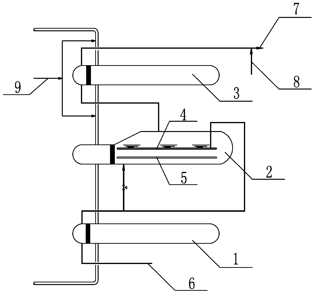
[0024] Embodiment 1 of the present invention: as figure 1 As shown, a steam generator includes a preheater 1, an evaporator 2 and a superheater 3, the preheater 1 and the evaporator 2 are connected through heat source pipes and water pipes, the evaporator 2 and the superheater 3 are connected through heat source pipes and Water pipe connection.
[0025] The lower end of the preheater 1 is provided with a steam generator feedwater port 6; the upper end of the superheater 3 is provided with a steam outlet 7; the steam outlet 7 is provided with a feedwater regulating device 8.
[0026] The heat source pipes at both ends of the superheater 3 are equipped with cold salt adjustment equipment 9; the head 11 is connected to the shell of the evaporator 2 by sliding;
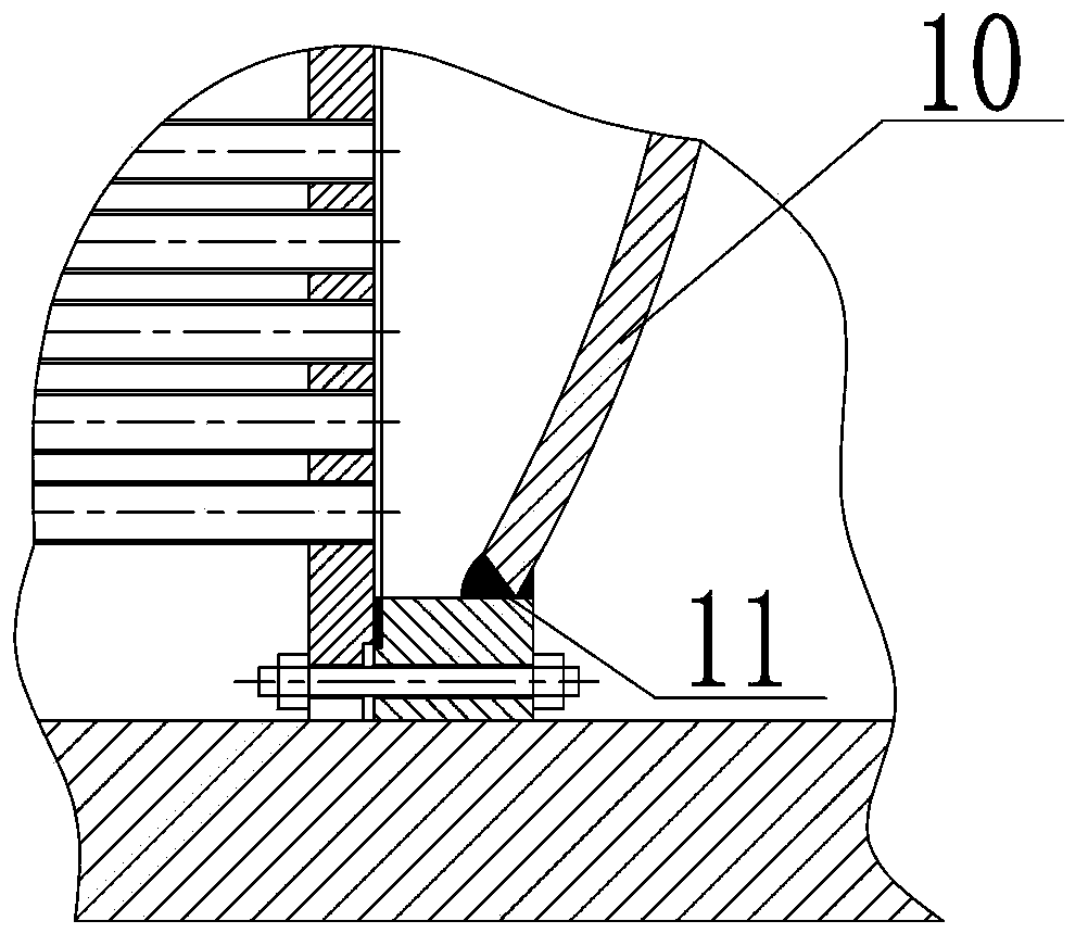
[0027] like figure 2 As shown, the evaporator 2 includes an upper separator 4 and a lower separator 5, and an evaporator floating head 10 is arranged behind the lower separator 5.
[0028] like image 3 As shown, a s...
Embodiment 2
[0029] Embodiment 2 of the present invention: as figure 1 As shown, a steam generator includes a preheater 1, an evaporator 2 and a superheater 3, the preheater 1 and the evaporator 2 are connected through heat source pipes and water pipes, the evaporator 2 and the superheater 3 are connected through heat source pipes and Water pipe connection.
[0030] The lower end of the preheater 1 is provided with a water supply port 6 for the steam generator; the upper end of the superheater 3 is provided with a steam outlet 7 .
[0031] The heat source pipes at both ends of the superheater 3 are equipped with cold salt adjustment equipment 9; the head 11 is connected to the shell of the evaporator 2 by sliding;
[0032] like figure 2 As shown, the evaporator 2 includes an upper separator 4 and a lower separator 5, and an evaporator floating head 10 is arranged behind the lower separator 5.
[0033] like image 3 As shown, a sealing head 11 is provided at the elbow on the floating h...
Embodiment 3
[0034] Embodiment 3 of the present invention: as figure 1 As shown, a steam generator includes a preheater 1, an evaporator 2 and a superheater 3, the preheater 1 and the evaporator 2 are connected through heat source pipes and water pipes, the evaporator 2 and the superheater 3 are connected through heat source pipes and Water pipe connection.
[0035] The heat source pipes at both ends of the superheater 3 are equipped with cold salt adjustment equipment 9; the head 11 is connected to the shell of the evaporator 2 by sliding;
[0036] like figure 2 As shown, the evaporator 2 includes an upper separator 4 and a lower separator 5, and an evaporator floating head 10 is arranged behind the lower separator 5.
[0037] like image 3 As shown, a sealing head 11 is provided at the elbow on the floating head 10 of the evaporator.
PUM
 Abstract
Description
Claims
Application Information
 - R&D
- Intellectual Property
- Life Sciences
- Materials
- Tech Scout
- Unparalleled Data Quality
- Higher Quality Content
- 60% Fewer Hallucinations
Browse by: Latest US Patents, China's latest patents, Technical Efficacy Thesaurus, Application Domain, Technology Topic, Popular Technical Reports.
© 2025 PatSnap. All rights reserved.Legal|Privacy policy|Modern Slavery Act Transparency Statement|Sitemap|About US| Contact US: help@patsnap.com


