Underframe of a railway concave flat car

A flat car, railway technology, applied in the direction of railway car body parts, chassis, transportation and packaging, etc., can solve the problems of low vertical rigidity of the chassis, fixed wheeled goods, can not use nailed triangle gear, etc., to increase the height range, increased stiffness, and the effect of avoiding interference

Active Publication Date: 2016-03-23
CRRC QIQIHAR ROLLING CO LTD
View PDF7 Cites 0 Cited by
  • Summary
  • Abstract
  • Description
  • Claims
  • Application Information

AI Technical Summary

Problems solved by technology

The middle concave bottom and the end of the D10 type railway concave-bottom flat car adopt an approximately right-angle transition mode, which has the disadvantage of inconvenient rolling and unloading of wheeled goods.
D11 and other railway concave bottom flatcars can realize self-rolling and rolling unloading, but because the concave bottom adopts no center beam structure, the vertical rigidity of the bottom frame is small and the bearing capacity is low
In addition, the existing railway concave-bottomed flat cars generally adopt a steel floor structure. After the wheeled vehicles are loaded, the wheeled goods cannot be fixed by means of nailing triangles, etc. Usually, more ropes are required for binding and reinforcement, so there are inconveniences in loading and reinforcement. shortcoming

Method used


Image

  • Underframe of a railway concave flat car
  • Underframe of a railway concave flat car
  • Underframe of a railway concave flat car

Examples


Embodiment Construction

[0017] The present invention will be described in detail below in conjunction with the accompanying drawings and embodiments.

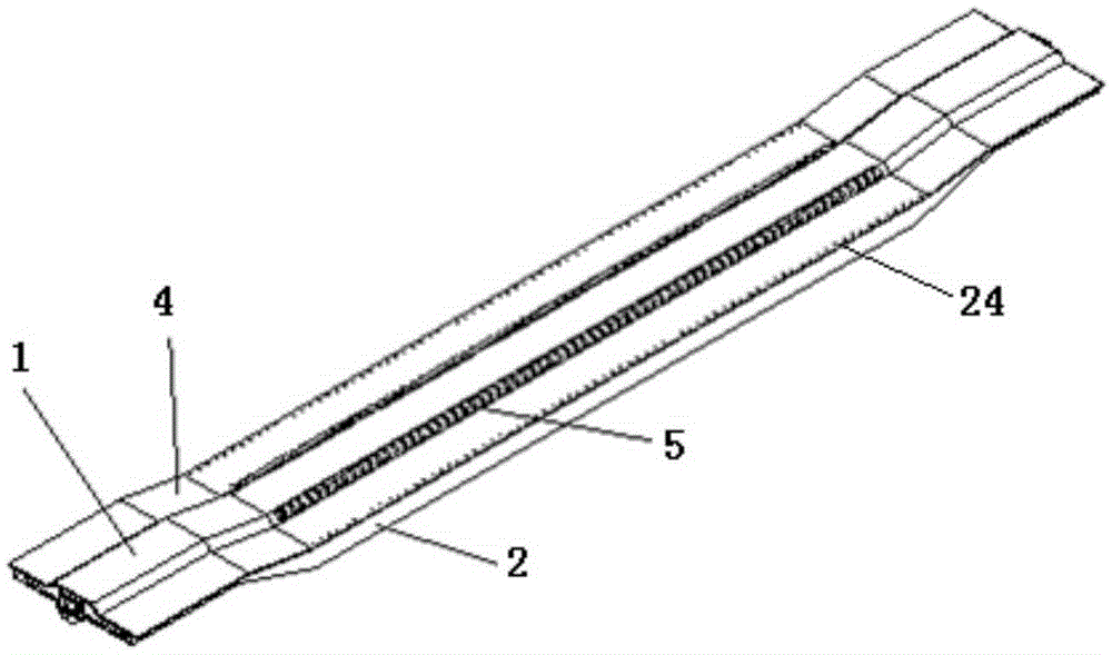
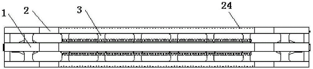
[0018] like figure 1 , figure 2 As shown, the present invention includes a middle beam 1, side beams 2, several transverse beams 3, a floor 4, two draw-in grooves 5 and a lower cover plate (not shown in the figure), wherein the middle beam 1 and the side beams 2 Both are concave structures in the middle, with slope transitions in the middle and both ends. The side beam 2 is fastened on both sides of the center beam 1 through several transverse beams 3 in parallel, the floor 4 is fastened to cover the center beam 1, the side beam 2 and the transverse beam 3, and the card slot 5 is fastened to the center beam 1 On the floor 4 on both sides of the concave bottom in the middle, the lower cover plate is fastened and connected under the concave bottom in the middle of the middle beam 1 and the side beam 2 .

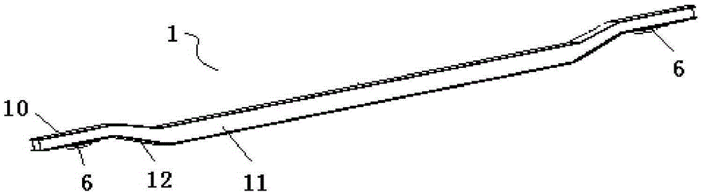
[0019] like image 3 As shown, the center s...


PUM


Abstract

The invention relates to a railway concave-bottomed flatcar chassis comprising a middle beam, side beams, transverse beams, and a floor plate. The side beams arranged on two sides of the middle beam are parallel to the middle beam. The middle beam and the side beams are fixedly connected through the transverse beams. The floor plate is arranged above the middle beam, the side beams and the transverse beams. Each of the middle beam and the side beams is in a concave-middle structure, with slope transitions between the middle and ends. Two locking channels are fixedly connected to the floor plate on two sides of the middle concave bottom of the middle beam respectively. The lower end of the middle concave bottom of the middle beam and the lower ends of the middle concave bottoms of the side beams are both fixedly connected with lower cover plates. Each of the middle beam and the side beams comprises an upper cover plate, webs vertically fixedly connected to the lower end of the upper cover plate, and one lower cover plate fixedly connected to the lower ends of the webs. Partitions are arranged between the webs of each of the middle beam and side beams for reinforcement. The outer side of the middle concave bottom of the upper cover of each side beam is provided with a row of holes, and each corresponding part of the floor plate above the side beams is also provided with a row of holes. The inner web of each side beam is shorter than the outer web of the corresponding side beam. The inner sides of two ends of the lower cover plate of each side beam are both provided with notches used for avoiding interference between the side beams and a bogie.

Description

technical field [0001] The invention relates to a railway wagon underframe, in particular to a railway concave bottom flat wagon underframe for transporting wheeled vehicles. Background technique [0002] Railway concave bottom flat cars are generally used to transport taller goods. The middle concave bottom and the end of the railway concave bottom flat car such as D10 adopt a transition mode approximately at a right angle, which has the disadvantage of being inconvenient for rolling and unloading wheeled goods. D11 and other railway concave-bottom flatcars can realize self-rolling and rolling-unloading, but because the concave bottom adopts a structure without a center beam, the vertical stiffness of the bottom frame is small and the load-carrying capacity is low. In addition, the existing railway concave-bottomed flat cars generally adopt a steel floor structure. After the wheeled vehicles are loaded, the wheeled goods cannot be fixed by means of nailing triangles, etc. ...

Claims


Application Information

Patent Timeline
Patent Type & Authority Patents(China)
IPC IPC(8): B61F1/00
Inventor 戴安国于世明张忠关雪梅王武建
Owner CRRC QIQIHAR ROLLING CO LTD
Why Eureka
Try Eureka