Roller-type LED panel fixing bracket

A fixed frame and roller-type technology, applied in the field of fixed frame, can solve problems such as difficult to put in, time-consuming and labor-intensive, hard damage of LED panel, etc., and achieve a stable effect in the process of putting in

Inactive Publication Date: 2014-05-28
DALIAN GONGDE TECH
View PDF0 Cites 1 Cited by
  • Summary
  • Abstract
  • Description
  • Claims
  • Application Information

AI Technical Summary

Problems solved by technology

[0002] Now the fixing frame of the large LED panel is generally directly embedded, which is time-consuming and laborious, and the installation cost is high. There is also a side opening type to put the LED panel in, but the process of putting in the LED panel is difficult, it is not easy to put in, and it is easy to cause the LED panel to be damaged.

Method used


Image

  • Roller-type LED panel fixing bracket

Examples


Embodiment Construction

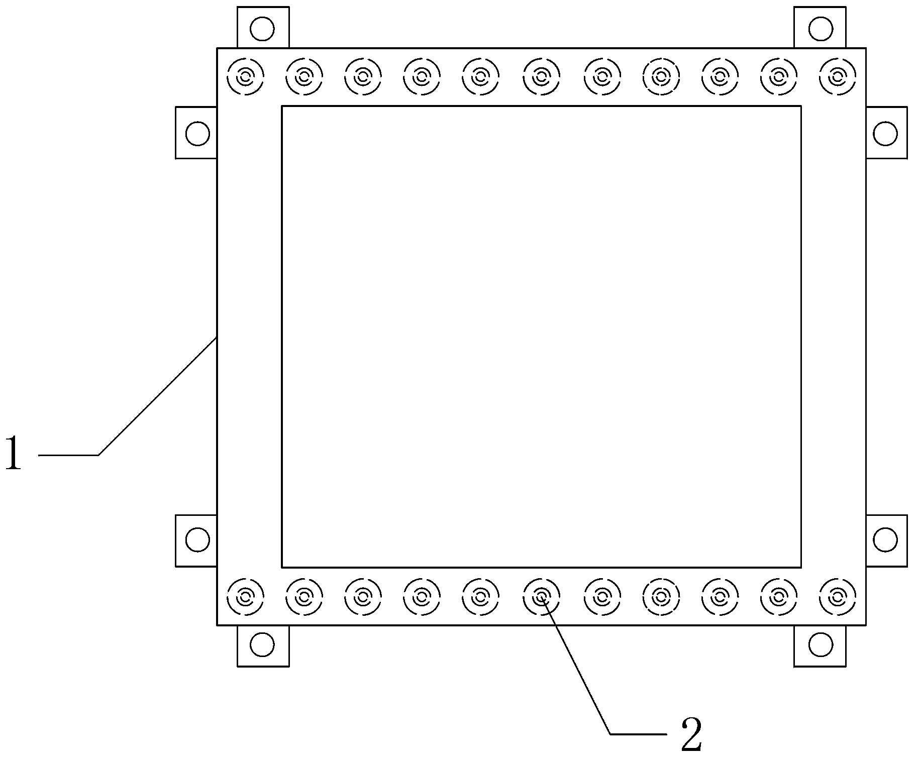
[0009] Such as figure 1 A roller-type LED panel fixing frame is shown, the fixing frame 1 is a rectangular frame, and the frame of the fixing frame 1 is processed with a ring groove with the same shape as the fixing frame 1, and the direction of the notch of the ring groove is toward the center of the fixing frame (1). direction; the roller 2 is installed in the ring groove; the bottom of the ring groove on at least one side of the frame of the fixed frame 1 and the wall of the ring groove are detachably fixedly connected; the roller 2 adopts a bearing roller, and the surface of the roller is made of soft rubber material;

[0010] The present invention adopting the above-mentioned technical solution realizes the insertion of the LED panel from the side by adopting the detachable manner of the ring groove and the side, that is, firstly remove the bottom of the detachable ring groove, and then insert the LED panel into the ring groove, at this time the ring groove The inner roll...


PUM


Abstract

The invention discloses a roller-type LED panel fixing bracket which is a rectangular frame. A circular groove in the same shape as the fixing bracket is processed in the frame of the fixing bracket, and the notch direction of the circular groove is towards the center direction of the fixing bracket. Rollers are mounted in the circular groove. The bottom of the circular groove in at least one edge of the frame of the fixing bracket is connected with the wall of the circular groove detachably and fixedly. Bearing rollers are adopted as the rollers, and the surfaces of the rollers are made of soft rubber. An LED panel is inserted in from the side face by adopting the circular groove and side face detachable mode, then the insertion process of the LED panel is assisted through the rollers arranged in the circular groove, when the LED panel is fixed in position, one bottom of the circular groove detached is mounted and fixed, and accordingly the LED panel is put in and fixed, and the put-in process is smooth and safe.

Description

technical field [0001] The invention relates to an LED panel fixing device, in particular to a fixing frame for putting the LED panel into the side opening and assisting the putting of the LED panel through rollers. Background technique [0002] Now the fixing frame of the large LED panel is generally directly embedded, which is time-consuming and laborious, and the installation cost is high. There is also a side opening type to put the LED panel in, but the process of putting in the LED panel is difficult, it is not easy to put in, and it is easy to cause the LED panel to be damaged. . Contents of the invention [0003] The technical problem to be solved by the present invention is to provide a fixing frame for putting the LED panel through the side opening and assisting the putting of the LED panel through the rollers. [0004] In order to achieve the above purpose, it is realized through the following technical solutions: [0005] A roller-type LED panel fixing frame,...

Claims


Application Information

Patent Timeline
Patent Type & Authority Applications(China)
IPC IPC(8): F21V21/00
Inventor 曲强
Owner DALIAN GONGDE TECH
Why Eureka
Try Eureka