
Multi-point lock with sequentially actuated locking elements

一种驱动元件、锁定元件的技术,应用在有弹簧栓的锁、建筑锁、建筑物紧固器件等方向,能够解决风险高等问题,达到强锁定力、简化锁舌和锁闩组件的效果

Inactive Publication Date: 2017-05-24
AMESBURY GROUP
View PDF8 Cites 0 Cited by
  • Summary
  • Abstract
  • Description
  • Claims
  • Application Information

AI Technical Summary

Problems solved by technology

The risk is very high for visitors to a residence or business, such as nannies or other caregivers

Method used


Image

  • Multi-point lock with sequentially actuated locking elements
  • Multi-point lock with sequentially actuated locking elements
  • Multi-point lock with sequentially actuated locking elements

Examples


Embodiment Construction

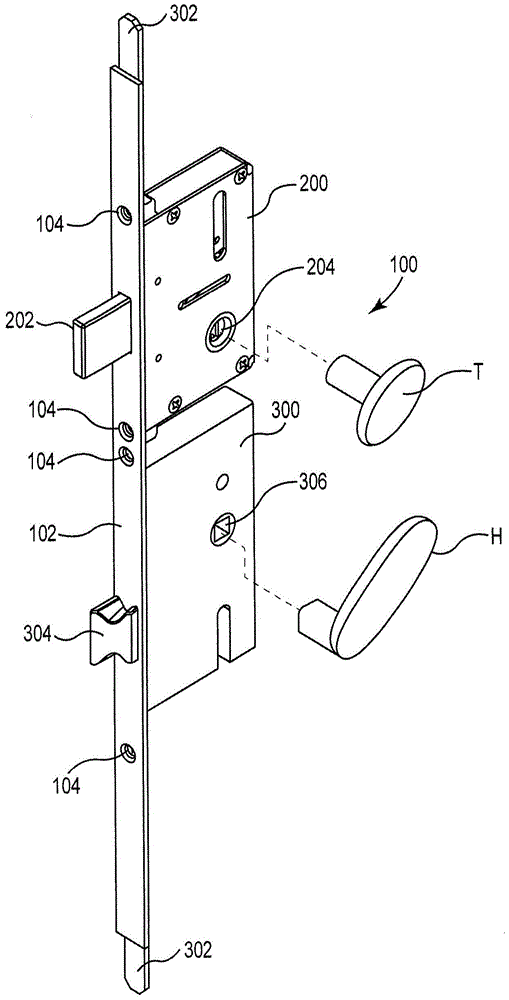
[0016] figure 1 A perspective view of a multi-point lock (MPL) 100 with multiple locking elements is shown. The MPL 100 includes a facestock or panel 102 to which a deadbolt housing 200 and a latch housing 300 are secured. The housing 200 , 300 is attached to the panel 102 by one or more screws, bolts or other fasteners 104 . Panel 102 covers an opening formed in the locking face of the door into which the various components of MPL 100 fit. One or more locking elements (bolts in the illustrated embodiment) 302 are actuated by a latch assembly located in the latch housing 300 so that they can move between locked and unlocked positions. Additionally, the latch 304 retractably protrudes from the latch housing 300 . The deadbolt 302 and the latch 304 may be actuated by one or more handles, knobs, or other devices located near the latch housing 300 . For example, in one embodiment, the handle H is operatively connected to the actuator 306 within the latch housing 300 . In a de...


PUM


Abstract

A lock includes a deadbolt assembly having a deadbolt and a deadbolt actuator. The lock also includes a deadbolt assembly separate from the deadbolt assembly. The latch assembly includes a latch and a latch actuator. The blocking element blocks actuation of the bolt from the unlocked position to the locked position when the bolt is in the retracted position. Alternatively or additionally, the blocking element may block actuation of the bolt from the locked position to the unlocked position when the bolt is in the extended position.

Description

[0001] This application is in the name of the Amesbury Group of Companies, Inc., a U.S. company of applicants in designated countries other than the United States, and U.S. citizens of Gray E. Tagtow, Tracy Lammers, Allen Rickenbaugh, Eric J. Adamson, Austin Hemmingsen, and Dan Raap, applicants designated only in the United States , filed as a PCT International Patent Application on July 17, 2012, and claiming priority to U.S. Patent Application for Invention, Application Serial No. 13 / 189,305, filed July 22, 2011, the subject matter of which is incorporated by reference in its entirety . Background technique [0002] Most consumers are already familiar with the operation of common single and double hole entry door locks having a handle for the deadbolt and a knob / cylinder for the deadbolt directly above the handle. However, lock systems for patio doors are very different from entry door locks. Patio systems often have a device for locking the door that can be handle actuated...

Claims


Application Information

Patent Timeline
Patent Type & Authority Patents(China)
IPC IPC(8): E05B63/14E05C9/00E05B17/20E05B63/18
CPCE05B17/2034E05B63/143E05B63/18E05B2015/0493E05C9/047Y10T70/5226Y10T70/523Y10T70/7582E05B15/04E05B59/00E05C9/04
Inventor 加里·E·塔格托特雷西·拉默斯艾伦·里肯鲍埃里克·J·亚当森奥斯丁·亨明森丹·拉普
Owner AMESBURY GROUP
Features
  • Generate Ideas
  • Intellectual Property
  • Life Sciences
  • Materials
  • Tech Scout
  • Unparalleled Data Quality
  • Higher Quality Content
  • 60% Fewer Hallucinations
Learn More