Light-emitting keyboard

A technology of light-emitting keyboards and keys, which is applied to electrical components, electrical switches, circuits, etc., can solve the problems of difficulty in thinning the light-emitting keyboard 10, increase the overall height of the light-emitting keyboard 10, etc., and achieve the effect of increasing convenience.

Inactive Publication Date: 2014-06-04
PRIMAX ELECTRONICS LTD
View PDF6 Cites 47 Cited by
  • Summary
  • Abstract
  • Description
  • Claims
  • Application Information

AI Technical Summary

Problems solved by technology

Setting the light source L and the light guide plate 18 under the membrane switch device 12 will increase the overall

Method used


Image

  • Light-emitting keyboard
  • Light-emitting keyboard
  • Light-emitting keyboard

Examples


Embodiment Construction

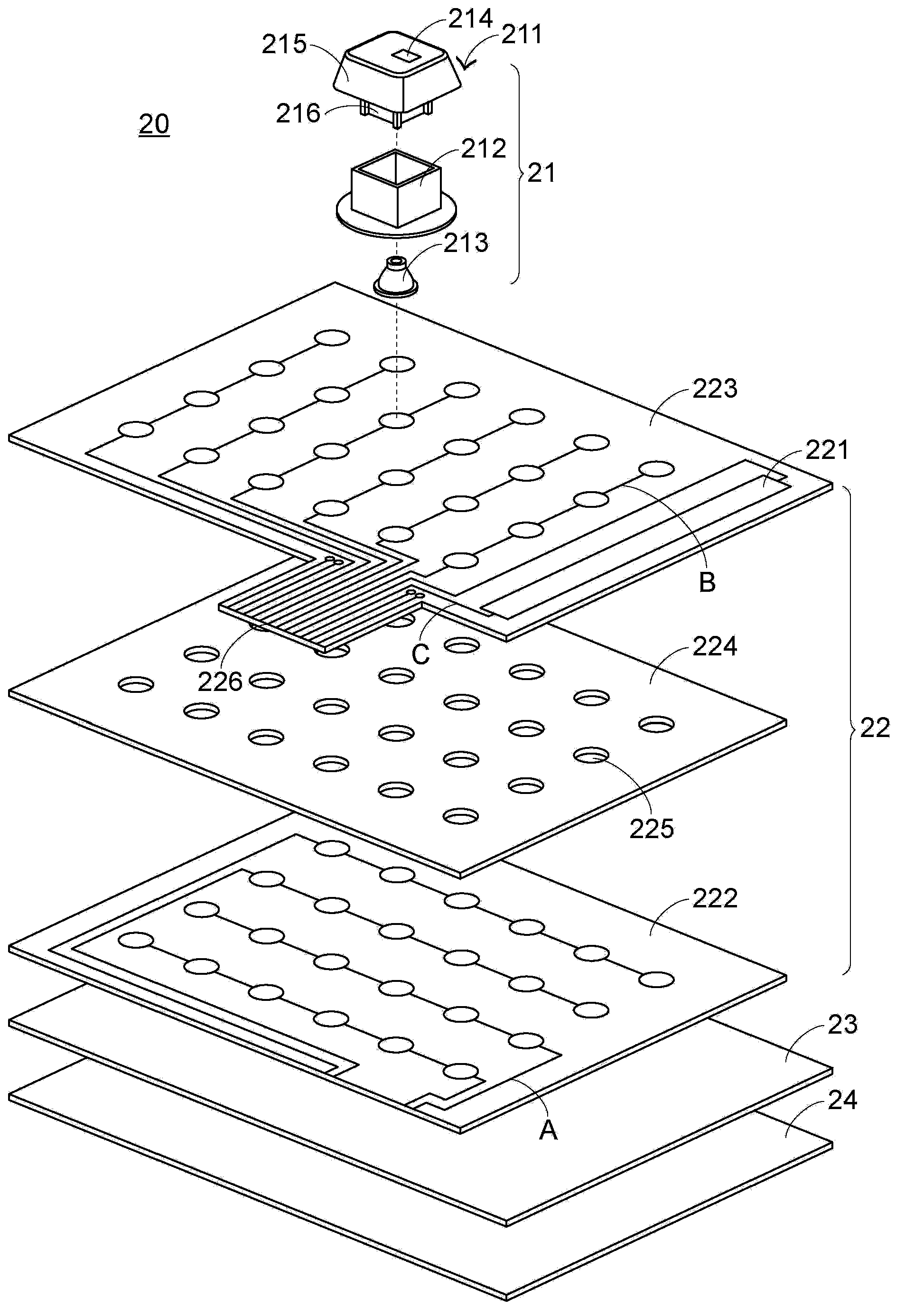
[0057] See figure 2 , figure 2 It is a schematic diagram of the first embodiment of the illuminated keyboard of the present invention. Such as figure 2 As shown, the illuminated keyboard 20 includes a key structure 21, a backlit membrane switch device 22, a reflective plate 23, and a bottom plate 24. The key structure 21 is used to be touched to trigger a key switch signal. When the user touches the key structure 21, a key switch signal will be triggered. The backlight membrane switch device 22 is disposed above the key structure 21 to provide light to the key structure 21.

[0058] The reflective plate 23 is disposed under the backlight membrane switch device 22 to reflect the light transmitted under the backlight membrane switch device 22, thereby reducing the light emission rate. The bottom plate 24 is arranged under the backlight membrane switch device 22, especially under the reflective plate 23, to support the key structure 21, the backlight membrane switch device 22, a...


PUM


Abstract

The invention discloses a light-emitting keyboard comprising a key structure and a backlight membrane switch device which comprises a light source, a light guide plate, a circuit board and a spacing board. The light guide plate comprises a first circuit layer. The circuit board comprises a second circuit layer and a light source circuit layer. The first circuit layer and the second circuit layer are used for generating a key switch signal. The light source circuit layer is used for driving the light source to emitting light. The first circuit layer is arranged on the light guide plate so that use amount of a substrate is reduced and the light-emitting keyboard is thinned. The second circuit layer and the light source circuit layer share connecting pins so that convenience in assembling the backlight membrane switch device is increased.

Description

Technical field [0001] The invention relates to a keyboard, in particular to a luminous keyboard. Background technique [0002] In order to make the keyboard easy to use in places with insufficient light, some keyboards currently on the market are equipped with light sources, such as light-emitting diodes (LEDs), to provide light to illuminate the keyboard, allowing keyboard users It is easy to recognize the words or symbols marked on the keys. [0003] See figure 1 , figure 1 It is a schematic diagram of an existing illuminated keyboard. Such as figure 1 As shown, the existing illuminated keyboard 10 includes a key structure 11, a membrane switch device 12, a backlight module 13, and a bottom plate 14. The membrane switch device 12 includes an upper circuit board 15, a lower circuit board 16, and a spacer board 17. . The backlight module 13 includes a light guide plate 18, a flexible circuit board 19 and a light source L. [0004] The button structure 11 is arranged above the me...

Claims


Application Information

Patent Timeline
IPC IPC(8): H01H13/83
Inventor 陈仲渊
Owner PRIMAX ELECTRONICS LTD
Why Eureka
Try Eureka