Passenger transferring device

A technology for passenger conveying equipment and frames, which is used in transportation and packaging, escalators, etc., can solve problems such as difficulty in effectively utilizing the relative displacement between the truss and the building, and expanding the relative displacement between the truss and the building.

Active Publication Date: 2014-06-11
HITACHI LTD
View PDF5 Cites 4 Cited by
  • Summary
  • Abstract
  • Description
  • Claims
  • Application Information

AI Technical Summary

Problems solved by technology

Therefore, it is difficult to effectively use the length of the truss supporting angle steel in the length direction of the truss to expand the relative displacement between the truss and the building
That is, in the truss supporting device of Patent Document 1, it is difficult to increase the relative displacement between the truss and the building (movable range of the frame) without increasing the length of the truss supporting member in the longitudinal direction of the truss.

Method used


Image

  • Passenger transferring device
  • Passenger transferring device
  • Passenger transferring device

Examples


no. 1 example

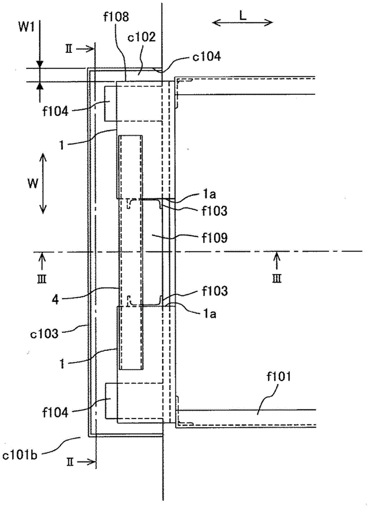
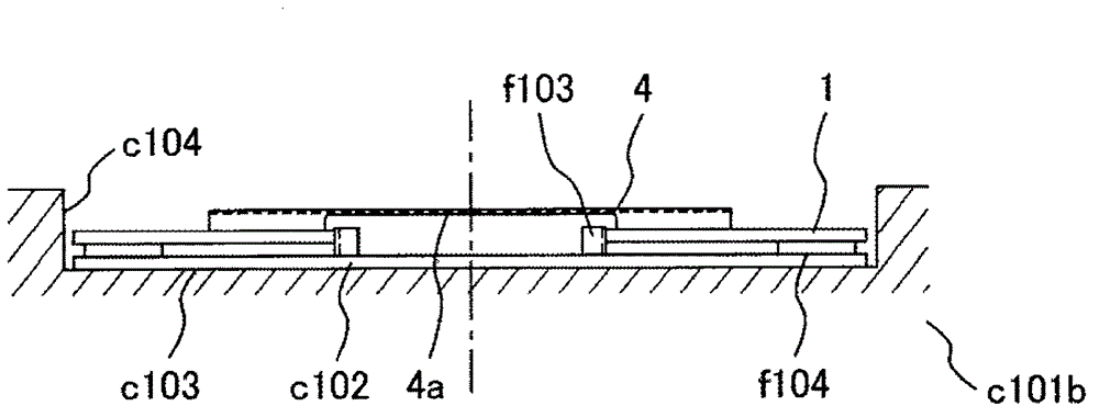
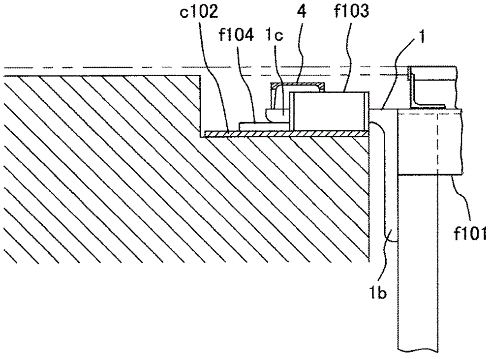
[0042] Refer to the following Figure 1 to Figure 3 The structure of the frame support part 1 of this embodiment is demonstrated. In describing this embodiment, refer to Figure 4 and Figure 5 , Figure 4 and Figure 5 The structure of the comparative example which has a movement restricting member on the outer side of a passenger conveyor is shown in .

[0043] figure 1 It is a plan view showing the support structure of the non-fixed side support portion of the passenger conveying equipment of this embodiment, figure 2 It is a side view of the supporting structure of the non-fixed side support part of the passenger conveying equipment viewed from the terminal direction of the passenger conveying equipment of this embodiment ( figure 1 II-II sectional view), image 3 It is a side view of the supporting structure of the non-fixed side support part of the passenger conveying equipment viewed from the width direction of the passenger conveying equipment of this embodimen...

no. 2 example

[0063] In this embodiment, on the basis of the structure of the first embodiment, the length of the second side 1c of the frame support portion 1 is further extended. The length of overlap between the building side support portion c103 and the frame body support portion 1 (hereinafter referred to as “overlap allowance”) can be extended by a length corresponding to the length of the extended portion of the second side 1c. Thus, in this embodiment, the shock resistance performance can be improved. In this manner, in this embodiment, there is a support structure for passenger conveyors in which the allowable overlap is extended.

[0064] Refer to the following Figure 7 to Figure 10 This embodiment will be described. Figure 7 It is a plan view showing the support structure of the non-fixed side support portion of the passenger conveying equipment of this embodiment, Figure 8 It is a side view of the supporting structure of the non-fixed side support part of the passenger con...

no. 3 example

[0078] In the first embodiment, the case where the two frame support parts are constituted by the L-shaped support angle steel fixed to the end of the frame f101 was explained as an example. The case where two frame support parts are constituted by an L-shaped support angle steel at the end of the frame f101 and a portion formed by extending a part of the main truss chord constituting the frame f101 will be described as an example.

[0079] In this embodiment, the L-shaped support angle steel is omitted, and the two frame body support parts ( not shown). At this time, the connection member 4 connects each part formed by extending a part of the main truss chord which is a frame support part. In addition, the movement restricting member restricts movement of a portion formed by extending a part of the main truss chord serving as the frame support portion. It should be noted that, in this embodiment, compared with the first embodiment and the second embodiment, there may be ins...


PUM


Abstract

The invention is aimed at providing a passenger transferring device capable of expanding a movable range of a frame body without increasing the arranged width and length of an arrangement portion of a support portion of the frame body. Due to the fact that the support portion of the frame body arranged at the end portion of the frame body is loaded on and supported by a building, in the passenger transferring device, the support portion of the frame body is provided with a first support portion of the frame body and a second support portion of the frame body which are arranged at different positions in a width direction of the frame body, connecting members for connecting the first support portion of the frame body and the second support portion of the frame body and movable limiting members arranged at building sides and connected with the support portion of the frame body and the second support portion of the frame body in an abutting mode to limit the frame body to move in a width direction. The movable limiting members are arranged at positions lower than the connecting members and between the first support portion for the frame body and the second support potion for the frame body to avoid inference with the connecting members.

Description

technical field [0001] The present invention relates to passenger conveying equipment including escalators, motorized walkways and the like. Background technique [0002] As the background technology of this technical field, Patent Document 1 discloses a truss support device for passenger conveyance equipment, which can support a truss to a building in such a manner that it does not enlarge the overall width dimension of the truss and allows the truss The movement in the length direction is to the specified size, but the movement in the width direction of the truss is not allowed (see paragraph 0009). [0003] This truss support device includes a truss support member attached to an end in the longitudinal direction of the truss, and a pallet provided in a building to support the truss support member. The truss support member is an angle steel material having an attachment flange attached to an end portion of the truss, and a support flange extending perpendicularly from the...

Claims


Application Information

Patent Timeline
IPC IPC(8): B66B23/00
Inventor 关口健太郎堀江宣孝宇津宫博文
Owner HITACHI LTD
Why Eureka
Try Eureka