Angle grinders with push-rod stop mechanism

A stopper mechanism and push rod technology, applied in portable grinding machines, grinding machines, manufacturing tools, etc., can solve the problems of limiting the use range of angle grinders, poor vision, and increasing the size of the head shell.

Active Publication Date: 2017-06-27
POSITEC POWER TOOLS (SUZHOU) CO LTD
View PDF2 Cites 0 Cited by
  • Summary
  • Abstract
  • Description
  • Claims
  • Application Information

AI Technical Summary

Problems solved by technology

[0005] Although the braking of the output shaft of the angle grinder head has been successfully realized in the prior art, since the button device or stop pin structure is arranged on the top or side of the head shell, it has the following defects: (1) The button device or stop pin The structure occupies a large volume, which increases the size of the head shell, so that the angle grinder cannot enter the narrow space, which limits the scope of use of the angle grinder; (2) The button device or stop pin structure is operated in the opposite direction to the removal direction of the grinding wheel, and the line of sight Not good, inconvenient to operate

Method used


Image

  • Angle grinders with push-rod stop mechanism
  • Angle grinders with push-rod stop mechanism
  • Angle grinders with push-rod stop mechanism

Examples


Embodiment Construction

[0017] Specific embodiments of the present invention will be described in detail below in conjunction with the accompanying drawings.

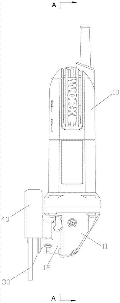
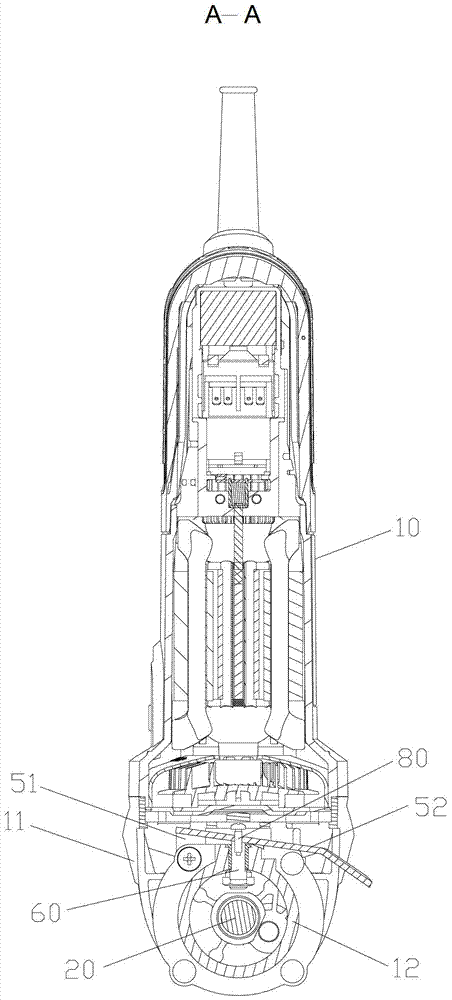
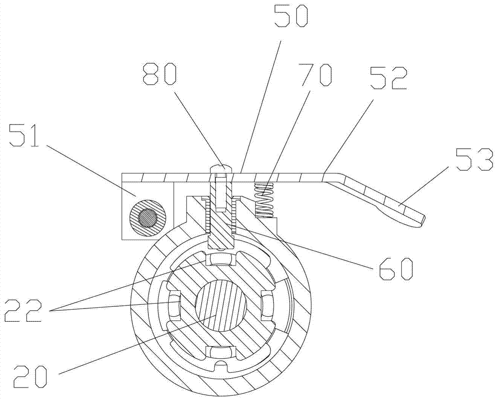
[0018] see Figure 1 to Figure 4 , the present invention provides an angle grinder with a push rod type stop mechanism, which includes an angle grinder body 10, a head shell 11, an output shaft 20 mounted on the head shell 11, and a drive for driving the output shaft 20 The gear 21 , the gear box cover 12 installed on the lower part of the head shell 11 , the grinding wheel sheet 30 , the grinding wheel cover 40 , and the push rod type stop mechanism includes a push rod 50 , a stop pin 60 and a spring 70 .

[0019] The push rod 50 is arranged on the outside of the reduction case cover 12, and one end thereof is a rotating shaft end 51 connected to the lower part of the reduction case cover 12 rotatably along a horizontal plane, and the other end thereof is used for pulling the reduction case cover 12. The free end 52 of the push rod 50 rotate...


PUM


Abstract

The invention provides an angle grinder with a push rod type stopping mechanism. The push rod type stopping mechanism is provided with a push rod, a stop pin and an elastic piece, wherein the push rod is arranged on the outer side of a reduction gearbox cover, one end of the push rod is connected with a rotation shaft end at the lower part of the reduction gearbox cover of the angle grinder and also can rotate along a horizontal plane, and the other end is used for pulling the rotary free end of the push rod; the stop pin is fixedly connected with the push rod, and the stop pin is arranged in the side wall of the reduction gearbox cover in a penetrating manner and also can move in radial direction; at least two grooves are respectively formed in the outer side, corresponding to the position of the stop pin, of a gear along the circumferential direction, and the stop pin can enter the grooves by moving in radial direction; the elastic piece is connected between the push rod and the reduction gearbox cover. Compared with prior art, the angle grinder with the push rod type stopping mechanism is simpler and more labor-saving in mounting and demounting of grinding wheels, and can reduce the size of the head shell.

Description

technical field [0001] The invention relates to an electric tool for grinding, cutting or polishing, in particular to an angle grinder with a push rod type stop mechanism. Background technique [0002] Angle grinder is a commonly used electric tool. Its main working principle is to use the grinding wheel piece fixed on the output shaft and rotate with the output shaft at high speed to process materials such as grinding, grinding and polishing. Since the grinding wheel of the angle grinder is easy to wear, the grinding wheel needs to be replaced frequently. When replacing the grinding wheel, it is necessary to fix the body of the angle grinder, clamp the output shaft with a wrench to brake, and then use another wrench to remove the fasteners that fix the grinding wheel. The replacement process is very troublesome and inefficient. [0003] Chinese utility model patent CN201239909Y discloses a working head of an angle grinder, which includes a head shell, a button device on th...

Claims


Application Information

Patent Timeline
Patent Type & Authority Patents(China)
IPC IPC(8): B24B23/02
CPCB24B23/028
Inventor 霍立祥吴海全
Owner POSITEC POWER TOOLS (SUZHOU) CO LTD
Why Eureka
Try Eureka