Automotive Air Conditioner Control Device
A technology of air conditioner and control device, which is applied to air handling equipment, brakes, vehicle components, etc., and can solve problems such as hard brake pedals
- Summary
- Abstract
- Description
- Claims
- Application Information
AI Technical Summary
Problems solved by technology
Method used
Image

Examples
Embodiment Construction
[0015] Embodiments of the present invention are described below with reference to the drawings.
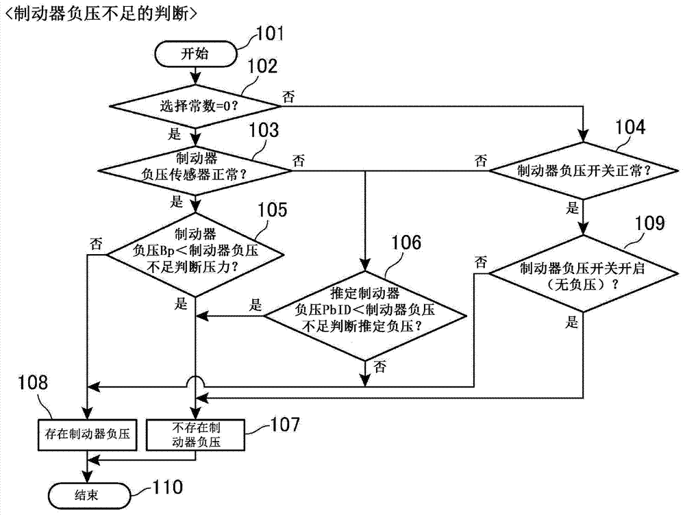
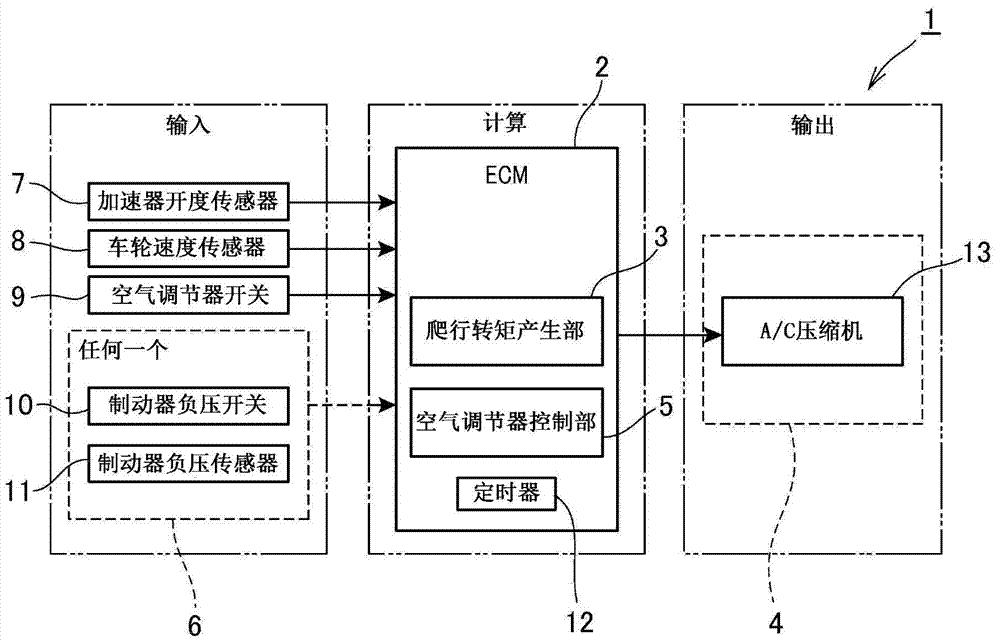
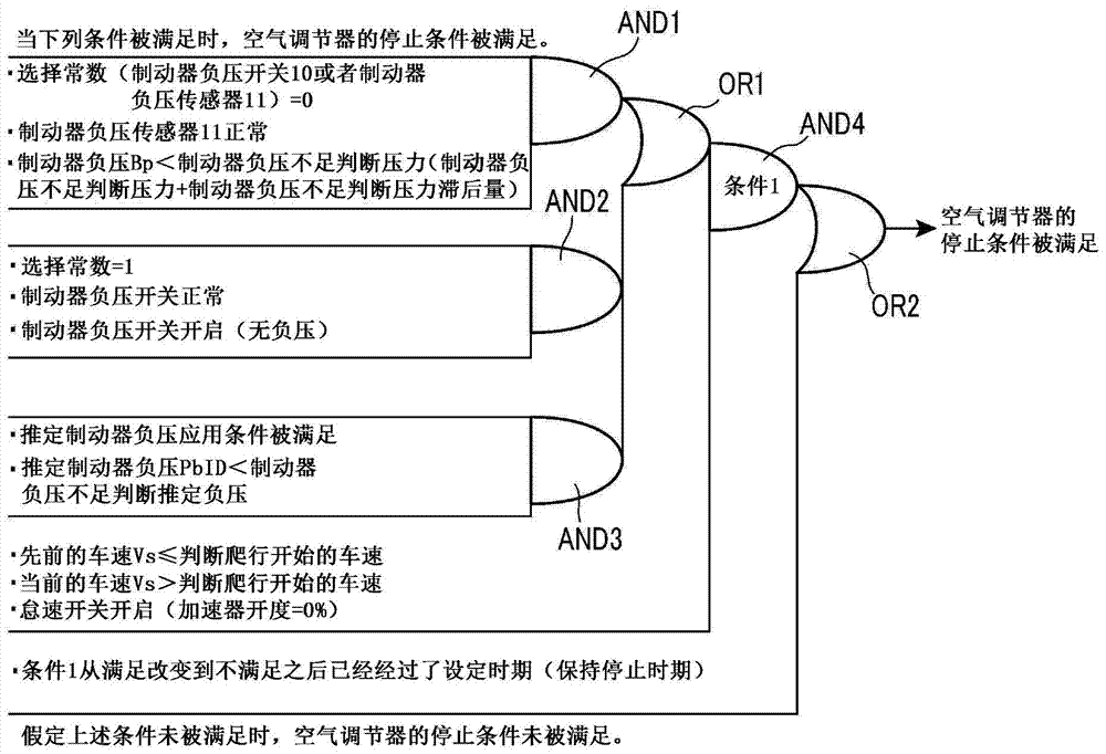
[0016] Figure 1 to Figure 5 Examples of the present invention are shown. Such as figure 2 As shown in , the vehicle air conditioner control device according to this embodiment includes: an "input" unit that outputs various detection signals to the control section 2 (also referred to as "ECM"); a "calculation" unit that includes A control section 2 to which various detection signals from an "input" unit are input; and an "output" unit to which a control signal from a "calculation" unit is input. The vehicle air conditioner control device 1 further includes: a creep torque generating portion 3 that generates drive torque for moving the vehicle even when the internal combustion engine (not shown) is in an idling state; an air conditioner 4, which is driven by power generated from an internal combustion engine; and an air conditioner control device 5 which controls the operating ...
PUM
 Abstract
Description
Claims
Application Information