Spring pressure friction gear mesh clutch

A spring pressure, clutch technology, applied in the field of clutch and gear transmission, can solve the problems of large volume, low power transmission efficiency, wide structure, etc., and achieve the effect of high transmission efficiency, optimized structure, and small volume

Active Publication Date: 2014-07-16
重庆尚平机械有限公司
View PDF5 Cites 12 Cited by
  • Summary
  • Abstract
  • Description
  • Claims
  • Application Information

AI Technical Summary

Problems solved by technology

[0002] Today's automobile clutches include friction clutches, fluid couplings, and electromagnetic clutches. They all use soft contact, that is, friction, hydraulic force, or electromagnetic force, to transmit the rotational power of the engine. The power transmission efficiency of these soft contacts is relatively high. Low; the reason why the modern developed automobile industry still uses the soft contact clutch method with low power transmission efficiency is because the meshed gears are difficult to separate when the gear meshing transmission rotates at high speed, and no hard transmission that is easy to mesh has not been found yet. The gear separation and gear meshing transmission method with higher transmission efficiency is a difficult problem in improving the transmission efficiency of automobiles; although Wei Boqing's invention patent "201410151795.6 Threaded Sleeve Clutch" can achieve high-efficiency transmission of gear clutch meshing, but its There is an intermediate driven wheel with a relatively wide structure and a relatively large volume. The present invention provides a structure with a small volume and high-efficiency transmission that can realize gear clutch engagement

Method used


Image

  • Spring pressure friction gear mesh clutch
  • Spring pressure friction gear mesh clutch
  • Spring pressure friction gear mesh clutch

Examples


Embodiment Construction

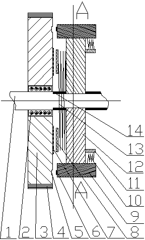
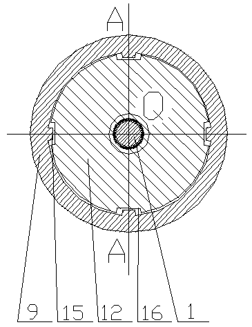
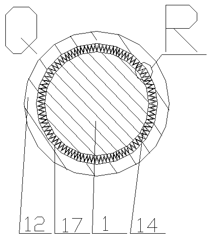
[0017] exist figure 1 In the embodiment shown in -4: the spring pressure friction gear engagement clutch comprises a driving shaft and a group of driving wheels and a group of driven wheels sleeved on the driving shaft; it is characterized in that: the right section of the driving shaft 1 has a driving Shaft saber teeth 14, a group of driving wheels are set on the driving shaft flower saber teeth 14, the driving wheel 12 has inner flower saber teeth 17 of the driving wheel, and the inner flower saber teeth 17 of the driving wheel are meshed with the driving shaft flower saber teeth 14, the driving The wheel 12 can move along the axial direction of the driving shaft 1, and the driving wheel 12 and the driving shaft 1 rotate at the same angular velocity; the outer circumference of the driving wheel 12 is equipped with a driving wheel outer wheel 9, and the outer circumference of the driving wheel 12 has a plurality of outer foil grooves 16 of the driving wheel , fit with a plura...


PUM


Abstract

A spring pressure friction gear mesh clutch comprises a driving shaft, a set of driving gears and a set of driven gears, wherein the driving shaft is sleeved with the driving gears and the driven gears. The spring pressure friction gear mesh clutch is characterized in that driving shaft spline teeth are arranged on the right segment of the driving shaft, the driving shaft spline teeth are sleeved with the driving gears, and spline teeth in the driving gears are meshed with the driving shaft spline teeth; driving gear outer gears are installed on the periphery of the driving gears, a plurality of driving gear outer spline grooves are arranged in the periphery of the driving gears and matched with a plurality of driving gear outer gear inner spline teeth on the inner circle of the driving gear outer gears in a sleeved mode, and the width of the driving gear outer spline grooves is larger than the width of the driving gear outer gear inner spline teeth; a powerful high-strength spring is fixedly installed on the left side of the driving gears, and a circle of side gears are arranged on the left end face of the driving gear outer gears; the driven gears are installed on the left segment of the driving shaft and connected with the driving shaft through inner bearings of the driven gears; a friction ring on the right side of the driven gears is installed on the right side face of the driven gears, and a circle of driven gear right teeth are arranged on the right side face, close to the periphery of the driven gears, of the driven gears.

Description

technical field [0001] The invention relates to a spring pressure friction gear meshing clutch, which is suitable for various mechanisms requiring clutch speed change and clutch speed regulation, such as clutch speed changers of various vehicles, gearboxes of lathes, etc., and belongs to the technical field of clutch and gear transmission. Background technique [0002] Today's automobile clutches include friction clutches, fluid couplings, and electromagnetic clutches. They all use soft contact, that is, friction, hydraulic force, or electromagnetic force, to transmit the rotational power of the engine. The power transmission efficiency of these soft contacts is relatively high. Low; the reason why the modern developed automobile industry still uses the soft contact clutch method with low power transmission efficiency is because the meshed gears are difficult to separate when the gear meshing transmission rotates at high speed, and no hard transmission that is easy to mesh ha...

Claims


Application Information

Patent Timeline
Patent Type & Authority Applications(China)
IPC IPC(8): F16D23/04F16D13/50
Inventor 魏伯卿
Owner 重庆尚平机械有限公司
Why Eureka
Try Eureka