Unlock instant, AI-driven research and patent intelligence for your innovation.
The Improved Structure of the Clamp Bar of the Forging Loading and Discharging Machine
What is Al technical title?
Al technical title is built by PatSnap Al team. It summarizes the technical point description of the patent document.
A technology for loading and unloading the clamp rod, which is applied in the direction of forging/pressing/hammer device, forging/pressing/hammering machinery, manufacturing tools, etc. It can solve the problems of poor flexibility, single action of the clamp rod, and large volume, and achieve high performance. Stable and reliable, increased angle range and compact size
Active Publication Date: 2015-08-05
山东荣升重型机械股份有限公司
View PDF8 Cites 0 Cited by
Summary
Abstract
Description
Claims
Application Information
AI Technical Summary
This helps you quickly interpret patents by identifying the three key elements:
Problems solved by technology
Method used
Benefits of technology
Problems solved by technology
Due to the single action of the clamp rod and poor flexibility, it cannot adapt to multi-angle operations
Although some improvements have been made to the action function of the pliers so far, most of them rely on the crank connecting rod structure, which is not only complex in structure and bulky, but also unable to adapt to frequent impacts of dynamic loads, poor fatigue resistance, and reliability. needs improvement
In addition, the driving form of the lifting and lowering of the clamp rod is hydraulic drive, limited by the formation of the hydraulic rod, the angle and stroke of the lifting and lowering of the clamp rod are limited
Method used
Image
Click on the blue label to locate the original text in one second.
Reading with bidirectional positioning of images and text.
Examples
Embodiment Construction
[0027] In order to facilitate the understanding of the technical solution of the present invention, the technical content involved in it will be further described below in conjunction with the accompanying drawings.
[0028] In describing the present invention, it should be noted that the orientation or position indicated by the terms "upper", "lower", "left", "right", "inner", "outer", "front", "back" etc. The relationship is based on the orientation or positional relationship shown in the drawings, and is only for the convenience of describing the present invention and simplifying the description, rather than indicating or implying that the referred device or element must have a specific orientation, be constructed and operated in a specific orientation, therefore It should not be construed as a limitation of the present invention.
[0029] In the description of the present invention, it should be noted that unless otherwise specified and limited, the terms "installation", "...
PUM
Abstract
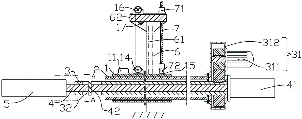
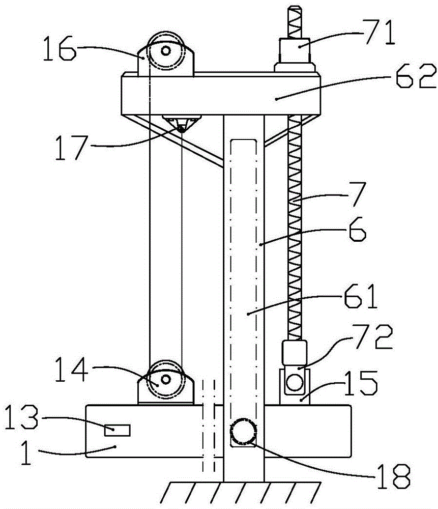
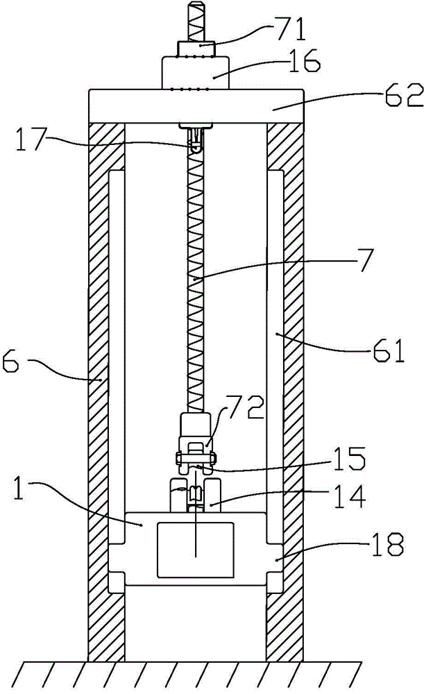
An improved structure of a claw beam of a forging charging and discharging machine comprises a guide barrel, a telescopic square barrel, a hollow shaft, a pull rod, a clamping oil cylinder, a clamp mechanism, a claw beam rotation driving device, a stand column and a nut and lead screw component, the guide barrel, the telescopic square barrel, the hollow shaft and the pull rod are coaxially arranged, the telescopic square barrel, the hollow shaft and the pull rod are connected with the claw beam rotation driving device to from an combined integral body, the combined integral body can move back and forth along with the movement of the telescopic square barrel, the hollow shaft and the pull rod can rotate in a plane perpendicular to the axial direction of the hollow shaft and the pull rod as a whole, meanwhile, the pull rod moves in the front-and-back direction relative to the hollow shaft, the hoisting mode that a shaft rolling steel wire rope and a lead screw are matched is adopted, and therefore relative to the hydraulic mode, the travel distance of the claw beam in the vertical direction is obviously increased. The movement function of clamping and releasing of a jaw in the clamp mechanism is not influenced, meanwhile, chuck rotation and stretching and contraction of the claw beam can be achieved, the inclination and bending angle and the vertical travel of the claw beam can be improved, the structure is simple, the size is compact, and the performance is stable and reliable.
Description
technical field [0001] The invention relates to the structure of the clamp rod part on the loading and unloading machine used in the forging production process, and belongs to the technical field of mechanical design. Background technique [0002] The domestic forging industry is currently under the dual pressure of overcapacity and the world financial crisis. If enterprises want to survive and develop in the current harsh situation, it is imperative to improve product quality and reduce production costs. Therefore, it is very necessary to improve the mechanization of production and reduce labor intensity and cost. [0003] At present, the loading and unloading machine for forging of automobile wheel hub is used to load the forged steel ingot or billet into the heating furnace, and can take the heated steel ingot or billet out of the heating furnace, and send it to the forging press or forging manipulator. . It is an important equipment in the forging process. The tong ba...
Claims
Application Information
Patent Timeline
Application Date:The date an application was filed.
Publication Date:The date a patent or application was officially published.
First Publication Date:The earliest publication date of a patent with the same application number.
Issue Date:Publication date of the patent grant document.
PCT Entry Date:The Entry date of PCT National Phase.
Estimated Expiry Date:The statutory expiry date of a patent right according to the Patent Law, and it is the longest term of protection that the patent right can achieve without the termination of the patent right due to other reasons(Term extension factor has been taken into account ).
Invalid Date:Actual expiry date is based on effective date or publication date of legal transaction data of invalid patent.

