Concrete Vibration Quality Monitoring Feedback Data Real-time Graphical Digital Communication Method

A technology of feedback data and communication methods, which is applied in the direction of error prevention/detection, electrical components, and transmission systems using return channels, and can solve problems such as increasing the probability of operator misoperation, reducing construction efficiency, and quality problems in concrete molding. Achieve accurate and efficient correction of defects, solve data packet loss, and improve the quality of vibrating operations

Active Publication Date: 2018-01-16
HOHAI UNIV +1
View PDF3 Cites 0 Cited by
  • Summary
  • Abstract
  • Description
  • Claims
  • Application Information

AI Technical Summary

Problems solved by technology

However, the traditional feedback methods in vibrating quality control at present only use voice or SMS communication through walkie-talkies or ordinary mobile phones, and when such information arrives at the scene, the operator needs to spend a long time on it due to poor intuitive readability. Only through understanding and communication can we confirm the positioning and vibration defect area and defect degree, and carry out follow-up correction work
For the continuous and uninterrupted pouring of concrete engineering operations, this method not only reduces the construction efficiency, but also causes defects not to be repaired in time due to the long time interval, resulting in quality problems of concrete molding
In addition, this method will also increase the probability of operator misoperation, such as misidentifying defective areas, failing to perform operations according to the required vibration time, etc.

Method used


Image

  • Concrete Vibration Quality Monitoring Feedback Data Real-time Graphical Digital Communication Method
  • Concrete Vibration Quality Monitoring Feedback Data Real-time Graphical Digital Communication Method
  • Concrete Vibration Quality Monitoring Feedback Data Real-time Graphical Digital Communication Method

Examples


Embodiment Construction

[0046] The accompanying drawings disclose, without limitation, the structural schematic diagrams of the preferred embodiments involved in the present invention; the technical solution of the present invention will be described in detail below in conjunction with the accompanying drawings.

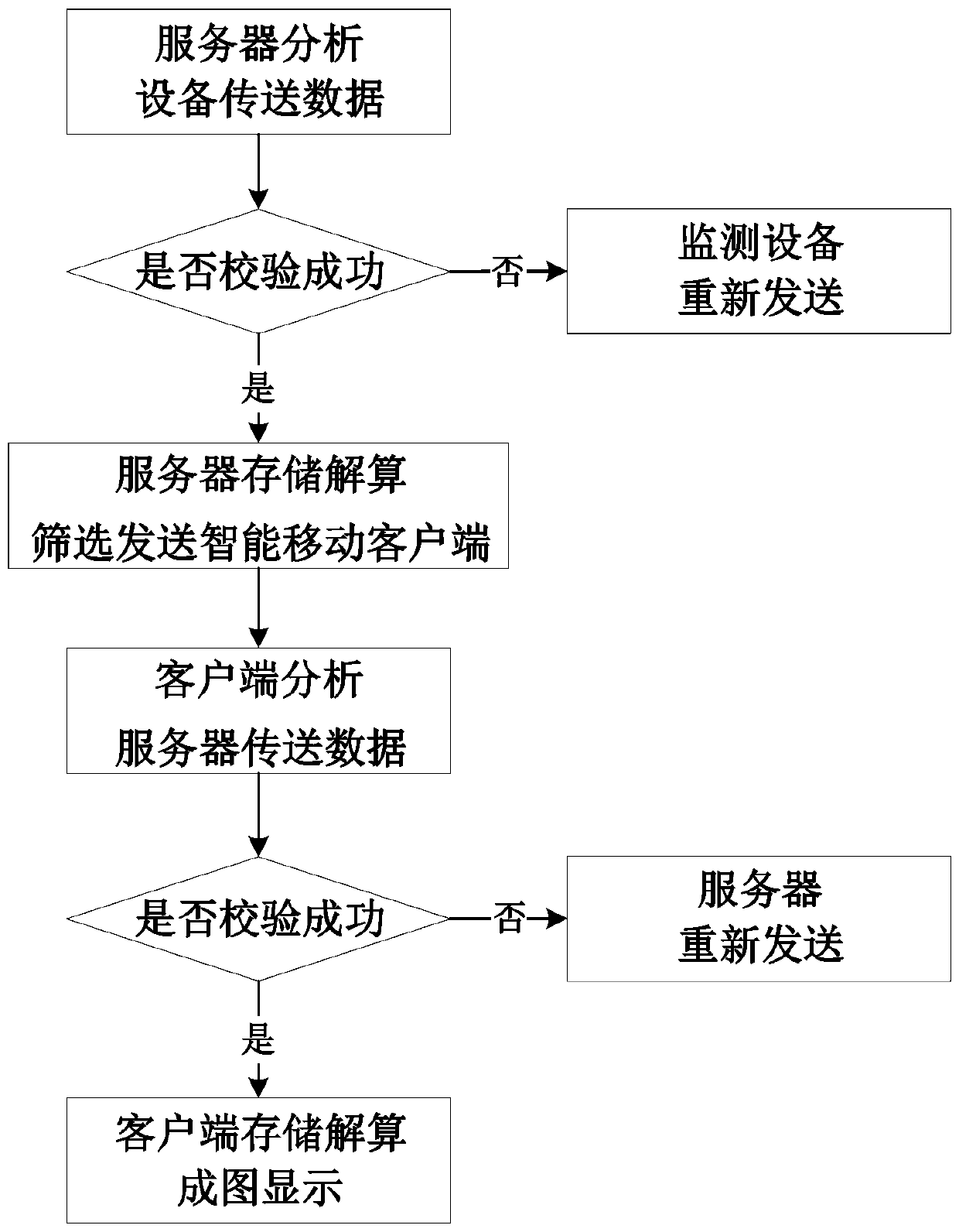
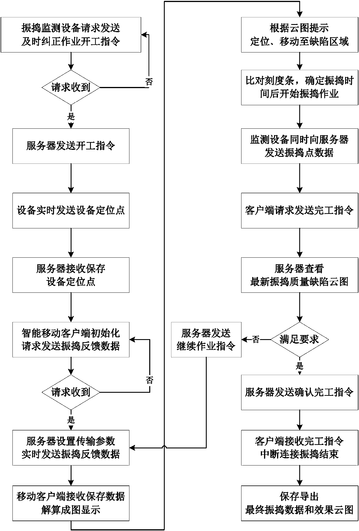
[0047] Such as Figure 1-2 As shown, a graphical digital communication method for monitoring feedback data of concrete vibrating quality according to the present invention includes the following steps: 1) After the vibrating operation is completed, the concrete vibrating monitoring equipment sends a request for correcting defects in time to the monitoring center server, Repeat the request until the server responds; 2) After receiving the request, the server sends a start-up instruction to the monitoring equipment; 3) After receiving the instruction, the monitoring equipment sends the device positioning data to the server in real time, and sends the vibration point data at the same time after...


PUM


Abstract

The invention provides a real-time graphic digital communication method of concrete vibrating quality monitoring feedback data. The real-time graphic digital communication method comprises developing a data communication module for correcting vibrating defects timely and embedding the data communication module into a field monitoring device so as to ensure that a vibrating device sends defect vibrating point data and device positioning data to a monitoring center timely through a 3G (The 3rd Generation Telecommunication) or GPRS (General Packet Radio Service) network when the corrected defects are fed back through the monitoring device timely; sending the data to an application of a field intelligent mobile client through the 3G or GPRS network after the data are stored, analyzed and processed through a server; performing graphing display on a vibrating defect quality cloud picture after the defect data information sent from a terminal monitoring center server is automatically received and calculated through the application timely. According to the real-time graphic digital communication method of the concrete vibrating quality monitoring feedback data, the field operating personnel can be guided to adjust and correct the vibrating defects timely, the defect data and graphics can be saved and obtained, the correction effect can be determined, and the quality of the vibrating work is improved.

Description

technical field [0001] The invention relates to a method for real-time graphic monitoring and feedback of concrete vibration quality through on-site intelligent mobile clients including smart phones or tablet computers for communication, and belongs to the field of concrete pouring quality control. Background technique [0002] Reliable testing and overall evaluation of the vibrating effect of fresh concrete pouring is one of the important links in concrete quality control. At present, the vibrating method adopted at the construction site is to consider the effective radius of the vibrating rods and insert them into the concrete in a staggered manner to ensure that the pouring area is basically vibrated and compacted. In practice, when workers move the vibrating point, they cannot accurately grasp the position / depth / duration of vibrating. It is often an empirical operation, which is highly random and is greatly affected by human factors and working conditions; / Over-vibrati...

Claims


Application Information

Patent Timeline
Patent Type & Authority Patents(China)
IPC IPC(8): H04L29/08H04L1/16H04L1/18E04G21/06
Inventor 田正宏边策蔡博文唐子龙
Owner HOHAI UNIV
Why Eureka
Try Eureka