Rotating and locking protection device

A technology of protective device and rotary buckle, which is applied in the direction of electrical components, electric switches, circuits, etc., can solve the problems of increased misoperation, complicated structure, and easy obstruction of operation by the protective cover, so as to reduce the probability of misoperation and reduce the complexity of operation Effect

Active Publication Date: 2014-08-06
SHANGHAI ELECTRICIAN IND & COMMERCE +1
View PDF3 Cites 0 Cited by
  • Summary
  • Abstract
  • Description
  • Claims
  • Application Information

AI Technical Summary

Problems solved by technology

Although the existing protective cover is also equipped with anti-closing measures, the structure is complex and occupies a large space, which is limited in the miniaturization and integration of control equipment.
Moreover, the protective cover that is opened during operation is likely to hinder the operation or injure the operator
In addition, the integrated control equipment has multiple switches. In order to o

Method used


Image

  • Rotating and locking protection device
  • Rotating and locking protection device
  • Rotating and locking protection device

Examples


Embodiment 1

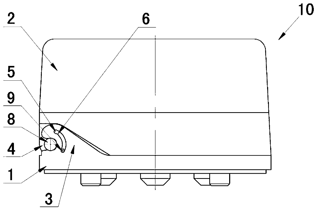
[0028] figure 1 It is a schematic structural diagram of the rotating fastening protection device according to the first embodiment of the present invention.

[0029] The rotation buckle protection device 10 includes a fixed structure and a rotation structure buckled with the fixed structure. Embodiment 1 is the application of the rotation buckle protection device 10 in the protection of a transfer switch. like figure 1 As shown, the fixed structure is the mounting plate 1 of the transfer switch, and the rotating structure is the protective cover 2 of the handle of the transfer switch.

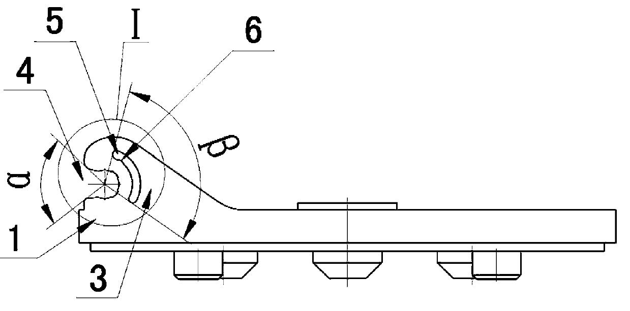
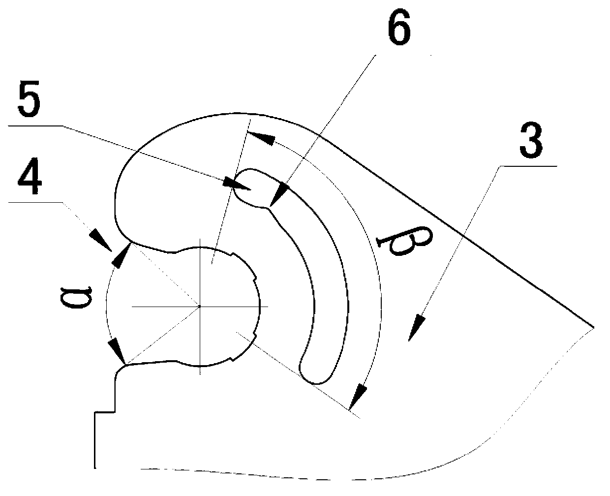
[0030] figure 2 It is a schematic structural diagram of the mounting board of Embodiment 1 of the present invention.

[0031] like figure 2 As shown, there is a positioning foot 3 on both sides of the mounting plate 1. The shape of the positioning foot 3 is like a right-angled trapezoid, that is, a wave shape. There is an open rotating port 4 on the positioning foot 3. There are a plural...

Embodiment 2

[0042] Image 6 It is a schematic diagram when the protective cover of the second embodiment of the present invention is closed.

[0043] Figure 7 It is a schematic diagram when the protective cover of the second embodiment of the present invention is fully opened.

[0044] like Image 6 , 7 As shown, in this embodiment, the rotary port 12 is closed, and there is a limiting groove 13 beside the rotary port 12 . There are a plurality of equidistant anti-slip bosses 14 on the limiting groove 13, and there are three in this embodiment. The other structures of the rotating fastening protection device 15 are the same as those in the first embodiment.

[0045] Figure 8 It is a partially enlarged view of the limiting groove of the second embodiment of the present invention.

[0046] like Figure 8 As shown, when the protective cover 19 is fully opened, the limit boss 16 slides to the point A of the limit groove 13, and stops there under the resistance of the anti-slip boss ...

Embodiment 3

[0053] Figure 9 It is a schematic diagram of the third embodiment of the present invention when the protective cover is closed.

[0054] Figure 10 It is a schematic diagram of the third embodiment of the present invention when the opening angle of the protective cover is 120°.

[0055] Figure 11 It is a schematic diagram of the third embodiment of the present invention when the opening angle of the protective cover is 90°.

[0056] like Figure 9 , 10 , 11, in this embodiment, the concave table 27 is a rectangle, the limit groove 28 is located on one side of the rotation port 21, and the angle between the two ends of the limit groove 28 and the center of the rotation port 21 is 14°. °. Since the limit groove is used to limit the maximum rotation angle of the protective cover, the protective cover in this embodiment can rotate between 0° and 120°. There are two middle anti-slip bosses 22 in the middle of the limit groove 28 . When the opening angle of the protective ...


PUM


Abstract

The invention discloses a rotating and locking protection device comprising a fixed structure and a rotating structure. Fixing feet are arranged on two sides of the fixed structure and are provided with rotating ports and limiting grooves, and anti-slip bosses are arranged in the limiting grooves. The rotating structure comprises a rotating boss and a limiting boss adopting the limiting grooves as a moving track. Since the anti-slip bosses are arranged in the limiting grooves, when a protection cover is opened, the limiting boss adopting the limiting grooves as the moving track is clamped in the limiting grooves through the anti-slip bosses so as to prevent the protection cover to slip and close, accidentally injures are eliminated, and operation complexity and false operation rate of control equipment can be reduced effectively.

Description

technical field [0001] The invention relates to a rotating buckle protection device, in particular to a rotation buckle protection device which prevents the rotating structure from slipping when it is opened. Background technique [0002] The rotating buckle protection device includes a fixed structure and a rotating structure buckled with the fixed structure, which can be used for the protection of the operating handle of the transfer switch. The fixed structure can be used as a mounting plate of the transfer switch for installing the transfer switch; the rotating structure can be used as a protective cover for the operating handle of the transfer switch and can be fastened on the fixed structure. When the protective cover and the mounting plate are fastened together, the operating handle of the transfer switch installed on the mounting plate is isolated from the external environment, thereby preventing the entry of dust or water vapor, which is conducive to the stable oper...

Claims


Application Information

Patent Timeline
IPC IPC(8): H01H9/04
Inventor 潘海峰陈小萍
Owner SHANGHAI ELECTRICIAN IND & COMMERCE
Why Eureka
Try Eureka