Supercharge Your Innovation With Domain-Expert AI Agents!

Cabinets with cable entries for various cable bundle thicknesses

A technology for wire inlets and cable bundles, which is applied in the direction of cabinets/cabinets/drawer components, etc., can solve the problems of difficult to seal the wire inlets tightly, and achieve the effect of fire prevention and rodent prevention

Active Publication Date: 2017-01-18
STATE GRID CORP OF CHINA +1
View PDF3 Cites 0 Cited by
  • Summary
  • Abstract
  • Description
  • Claims
  • Application Information

AI Technical Summary

Problems solved by technology

When the gap after passing through the cable bundle is large, it is often difficult to seal the cable inlet hole tightly for the installation site with fireproof and rodent-proof sealing requirements

Method used


Image

  • Cabinets with cable entries for various cable bundle thicknesses

Examples


specific Embodiment approach 1

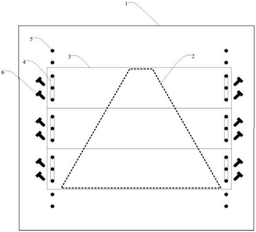
[0010] Specific implementation mode one: combine figure 1 Describe the present embodiment, the cabinet with the wire inlet hole that adapts to the thickness of various cable bundles described in this embodiment includes a cabinet door, and the cabinet door includes a door panel 1, N sliding cover plates 3 and M bolts 6 ; The door panel 1 is provided with a trapezoidal wire inlet hole 2, and a row of threaded fixing screw holes 5 are arranged at equal intervals on the door panel 1 on both sides of the trapezoidal wire inlet hole 2;

[0011] Both sides of each sliding cover plate 3 are respectively provided with cover plate screw holes 4, the width of the cover plate screw holes 4 is the same as the width of the fixed screw hole 5, the position of the cover plate screw holes 4 on both sides of the sliding cover plate 3 Corresponding to the positions of the two rows of fixing screw holes 5 on the door panel 1 respectively;

[0012] The bolt 6 is used to fix the sliding cover pla...

specific Embodiment approach 2

[0014] Specific Embodiment 2: This embodiment is a further limitation of the cabinet with wire inlet holes that adapt to the thickness of various cable bundles described in Specific Embodiment 1. In a row of fixing screw holes 5 adjacent two The spacing is a quarter of the width of the sliding cover.

specific Embodiment approach 3

[0015] Specific embodiment 3: This embodiment is a further limitation of the cabinet with wire inlet holes adapting to the thickness of various cable bundles described in specific embodiment 2. The screw holes 4 on the cover plate are elongated, and the The length of the cover plate screw hole 4 is half of the length of the sliding cover plate 3 .

[0016] In this embodiment, there are multiple sliding cover plates 3, and the cover plate screw holes 4 on both sides are elongated. After the fixing bolts are loosened, they can slide back and forth, and the distance that can slide back and forth exceeds one-half of the width of the sliding cover plate 3. , so that the sealing position of the cover plate can be continuously adjusted throughout the entire trapezoidal height range.

[0017] The bottom fixing screw holes 5 with threads are arranged on both sides of the cable inlet hole of the cabinet. The spacing between the bottom fixing screw holes is 1 / 4 of the width of the slidin...


PUM


Abstract

The invention relates to a cabinet, in particular to a cabinet with a wire inlet hole adapting to wire bundles of various thicknesses. The cabinet aims to solve the problem that a large gap is generated after wire bundles penetrate through a wire inlet hole of an existing cabinet. The cabinet comprises a cabinet door. The cabinet door comprises a door board, N sliding cover boards and M bolts. The door board is provided with the trapezoid wire inlet hole. The portions, on the two sides of the trapezoid wire inlet hole, of the door board are respectively provided with a row of fixing screw holes at equal intervals, wherein each fixing screw hole is provided with threads. The two sides of each sliding cover board are respectively provided with a cover board screw hole. The width of each cover board screw hole is the same as that of each fixing screw hole. The cover board screw holes in the two sides of the sliding cover boards correspond to the two rows of fixing screw holes in the door board in position. The bolts are used for passing through the cover board screw holes and the fixing screw holes to fix the sliding cover boards. M and N are respectively a positive integer. The cabinet is applicable to cabinets with wire inlet holes controllable in size.

Description

technical field [0001] The invention relates to a cabinet. Background technique [0002] At present, there are mainly two types of cable entry holes in the cabinet. One is a pre-opened round hole with a fixed diameter. If the cable bundle is thin, there will be a large gap. If the cable bundle is thick, it will be difficult to pass through. . The other is a rectangular opening, the opening is relatively large, and one or more cover plates are used to control the size of the opening. This type of opening is often relatively large, and there will be a large gap on both sides when the cable bundle passes through. When the gap after passing through the cable bundle is large, it is often difficult to seal the cable inlet hole tightly for installation sites with fireproof and rodent-proof sealing requirements. Contents of the invention [0003] The purpose of the present invention is to solve the problem of large gaps after the wire inlet hole of the current cabinet passes thr...

Claims


Application Information

Patent Timeline
Patent Type & Authority Patents(China)
IPC IPC(8): H05K5/02H05K5/03
Inventor 赵威赵琳李明
Owner STATE GRID CORP OF CHINA
Features
  • R&D
  • Intellectual Property
  • Life Sciences
  • Materials
  • Tech Scout
  • Unparalleled Data Quality
  • Higher Quality Content
  • 60% Fewer Hallucinations
Learn More