Machine tool fixture and machine tool using the machine tool fixture

A technology of machine tool fixtures and machine tools, which is applied in the direction of chucks, etc., can solve the problems of small alignment range, etc., and achieve the effect of large alignment range, convenient use, and convenient alignment

Active Publication Date: 2016-08-17
HENAN AEROSPACE HYDRAULIC & PNEUMATIC TECH
View PDF5 Cites 0 Cited by
  • Summary
  • Abstract
  • Description
  • Claims
  • Application Information

AI Technical Summary

Problems solved by technology

[0003] The object of the present invention is to provide a machine tool fixture to solve the problem that the alignment range of the existing machine tool fixture is small; at the same time, the present invention also provides a machine tool using the machine tool fixture

Method used


Image

  • Machine tool fixture and machine tool using the machine tool fixture
  • Machine tool fixture and machine tool using the machine tool fixture
  • Machine tool fixture and machine tool using the machine tool fixture

Examples


Embodiment Construction

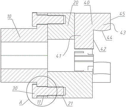
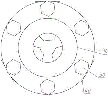
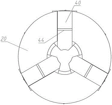
[0020] An embodiment of the machine tool fixture in the present invention is as Figure 1~Figure 4 As shown, it includes a spindle connection plate 10 for transmission connection with the spindle of the machine tool, a chuck 20 fixed on the spindle connection plate 10 by bolts 30 and three claws 40 arranged on the chuck 20 .

[0021] The main shaft connection plate 10 is provided with a flange structure, and the flange structure is provided with a bolt perforation 11 for the bolt 30 to pass through, and the chuck 20 is provided with a threaded hole 21, and the bolt 30 passes through the bolt hole. 11 is passed through and then screwed into the threaded hole 21 on the chuck 20 to realize the fixed and transmission connection between the main shaft connection plate 10 and the chuck 20 . The diameter of the bolt hole 11 on the main shaft connection plate 10 is larger than the diameter of the bolt 30, thereby forming a set gap δ between the bolt 30 and the inner wall of the bolt h...


PUM


Abstract

The invention relates to a machine tool clamp and a machine tool using the machine tool clamp. The machine tool clamp comprises a chuck and a clamping jaw, wherein the clamping jaw is arranged on the chuck, the axis of the chuck extends in the front and back direction, the clamping jaw is provided with a clamping surface for clamping a workpiece, the clamping surface is a spherical surface or an arc surface, the spherical surface protrudes towards the rotary center of the clamping jaw, the arc surface protrudes towards the rotary center of the clamping jaw, and the rotary axis of the arc surface is vertical to the front and back direction. When the workpiece is clamped, the clamping surface of the clamping jaw is in the point contact with the workpiece, so the workpiece can be adjusted with larger inclining amount, and the workpiece can be conveniently aligned. Compared with the prior art, the machine tool clamp has the advantages that the structure is simple, the convenience in manufacturing and use is realized, the alignment range is large, and the end surface of the workpiece is conveniently aligned.

Description

technical field [0001] The invention relates to a machine tool fixture and a machine tool using the machine tool fixture. Background technique [0002] Machine tool clamps are generally required to clamp the workpiece on the machine tool. The commonly used machine tool clamps in the prior art, such as three-jaw chucks and four-jaw chucks, all include chucks used to drive the main shaft of the machine tool and are arranged on the chucks. The jaws on the jaw have a clamping surface for clamping the workpiece, and clamp and fix the workpiece during work, so that the workpiece can rotate with the chuck and the spindle. In the prior art, the clamping surface of the claw is a plane or an arc surface whose rotation axis is parallel to the axial direction of the chuck. When the workpiece is clamped, the claw and the workpiece are in surface contact or line contact along the axial direction of the chuck. When clamping, although the workpiece can move a lot along the axial direction ...

Claims


Application Information

Patent Timeline
Patent Type & Authority Patents(China)
IPC IPC(8): B23B31/103
CPCB23B31/103
Inventor 周新利刘宝林张成立张晓磊邵真贵
Owner HENAN AEROSPACE HYDRAULIC & PNEUMATIC TECH
Why Eureka
Try Eureka