
Angle measuring device

An angle measuring device and mass body technology, applied in the direction of measuring devices, components of the damping parts of the measuring devices, optical devices, etc., can solve problems such as motor heating and motor efficiency reduction

Active Publication Date: 2017-11-24
DR JOHANNES HEIDENHAIN GMBH
View PDF7 Cites 0 Cited by
  • Summary
  • Abstract
  • Description
  • Claims
  • Application Information

AI Technical Summary

Problems solved by technology

This in turn leads, for example, to whistling noises and to excessive motor heating and thus to a reduction in motor efficiency

Method used


Image

  • Angle measuring device
  • Angle measuring device
  • Angle measuring device

Examples


Embodiment Construction

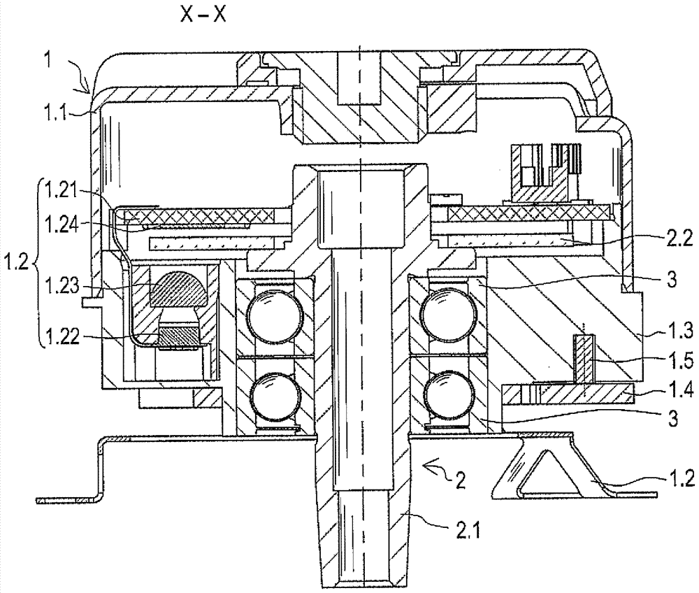
[0029] in figure 1 The angle measuring device shown in includes a stator 1 and a rotor 2. The rotor 2 has a shaft 2.1 for coupling to a structural element to be measured in a rotationally fixed manner, for example to a motor shaft. The connection between the shaft 2.1 of the angle measuring device and the motor shaft is realized, for example, by a connecting device in the form of a fastening bolt extending through the shaft 2.1, wherein the end of the shaft 2.1 is The part is designed conically. Therefore, the relative angular position or rotational movement between the stator 1 and the rotor 2 can be determined by the angle measuring device. This angle measuring device is also often referred to as a rotation generator.

[0030] The shaft 2.1 is rotatably supported by a bearing, here two rolling bearings 3, inside a body 1.3, which is assigned to the stator 1. A code disc 2.2 arranged inside the angle measuring device is fastened to the shaft 2.1.

[0031] The stator 1 includes...


PUM


Abstract

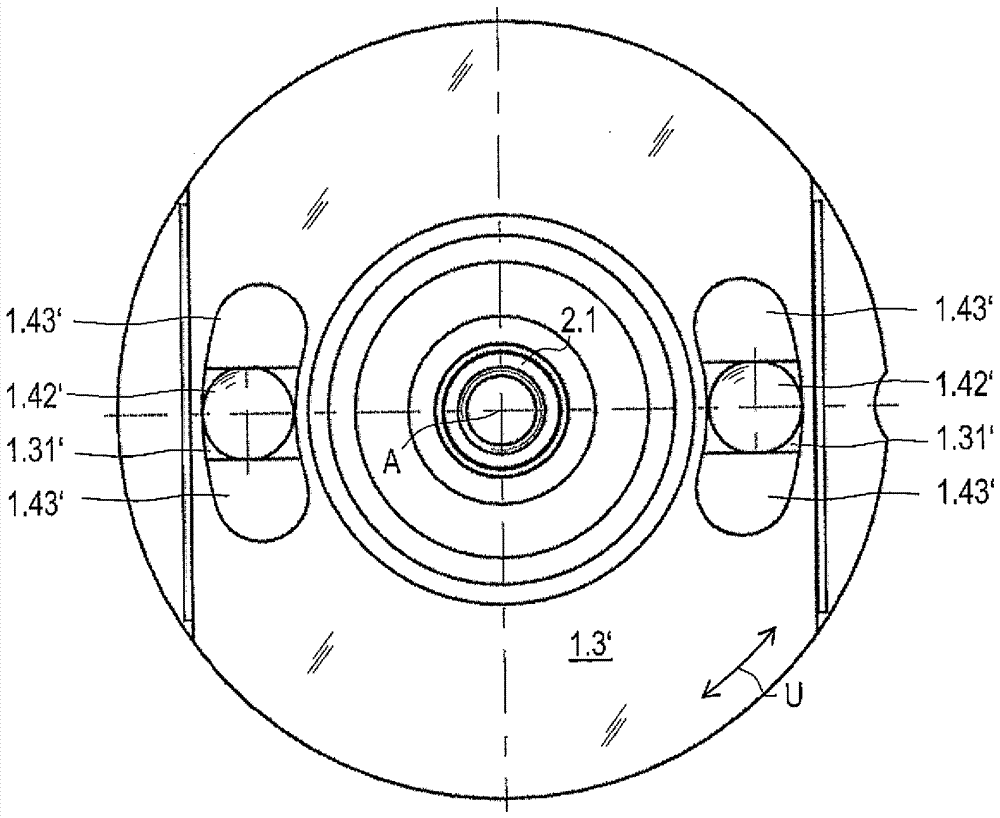
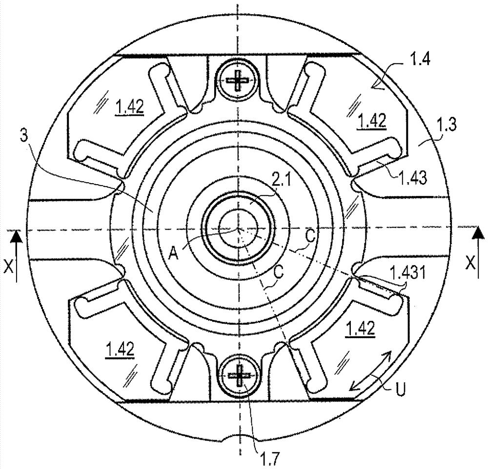
The invention relates to an angle measuring device with a stator (1) and a rotor (2), wherein the rotor (2) is relative to the stator (1) around an axis (A) along a circumferential direction (U ) are rotatably arranged. The rotor (2) has a shaft (2.1), on which a code disc (2.2) is fastened in a rotationally fixed manner. The stator (1) has a body (1.3; 1.3'; 1.3'') and a scanning device (1.2) for scanning the code disc (2.2). For vibration damping, the angle measuring device has a pendulum mass (1.42; 1.42'; 1.42'') connected to the body (1.3; 1.3'; 1.3''), the pendulum mass with a A direction component parallel to the circumferential direction (U) is deflectable relative to the body (1.3; 1.3'; 1.3'').

Description

Technical field [0001] The invention relates to an angle measuring device according to claim 1. Background technique [0002] Angle measuring devices, often also called rotation generators, are used to measure the rotational movement of a rotatably supported body via one or more revolutions. Here, the rotational movement is detected incrementally or absolutely. Combined with rack and pinion, or combined with threaded spindle, linear motion can also be measured using an angle measuring device. [0003] This angle measuring device is often used in combination with an electric motor. In order to balance the alignment error or axial misalignment between the supported shaft of the angle measuring device and the associated electric motor, compensation couplings are often used. It can be arranged between the shaft of the angle measuring device and the electric motor, or be configured as a so-called stator coupling. A stator coupling elastically connects the stator of the angle measuri...

Claims


Application Information

Patent Timeline
Patent Type & Authority Patents(China)
IPC IPC(8): G01B11/26
CPCG01D11/10F16F15/1421
Inventor H.迈尔
Owner DR JOHANNES HEIDENHAIN GMBH
Learn More