Tool position planning method for five-axis multi-row side milling

A tool position, side milling technology, applied in the direction of electrical program control, digital control, etc., can solve the problem of not being able to use one side milling tool, difficult to improve processing efficiency and surface quality at the same time, and large space distortion.

Active Publication Date: 2016-12-07
SHANGHAI JIAOTONG UNIV
View PDF8 Cites 0 Cited by
  • Summary
  • Abstract
  • Description
  • Claims
  • Application Information

AI Technical Summary

Problems solved by technology

The blades of axial flow impellers are usually designed as free-form surfaces with large spatial distortions, which cannot be formed by one side milling pass
At present, point milling is often used, and it is difficult to improve processing efficiency and surface quality at the same time

Method used


Image

  • Tool position planning method for five-axis multi-row side milling
  • Tool position planning method for five-axis multi-row side milling
  • Tool position planning method for five-axis multi-row side milling

Examples


Embodiment Construction

[0055] The present invention will be described in detail below in conjunction with specific embodiments. The following examples will help those skilled in the art to further understand the present invention, but do not limit the present invention in any form. It should be noted that those skilled in the art can make several modifications and improvements without departing from the concept of the present invention. These all belong to the protection scope of the present invention.

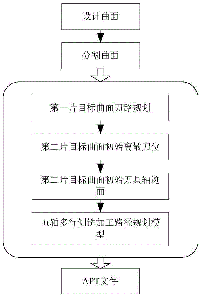
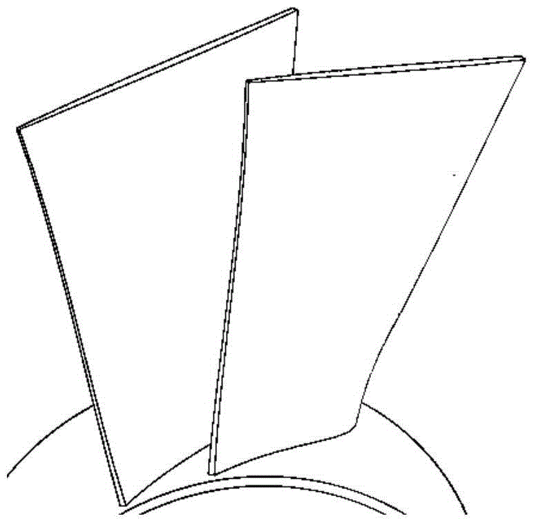
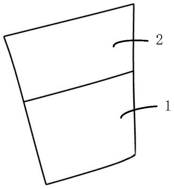
[0056] In this example, if figure 1 , figure 2 , image 3 , Figure 4 as well as Figure 5 As shown, the present invention establishes the tangential continuous condition of the envelope surfaces of two adjacent rows of cutters by utilizing the double-parameter spherical family envelope theory.

[0057] According to the double-parameter spherical family envelope theory, the envelope surface of two adjacent rows of cutters is expressed as

[0058] x (i) (a,t)=S (i) (a,t)+r(a)n (i) (a,t),(a...


PUM


Abstract

The invention provides a five-axis multi-row flank milling cutter position planning method. The method includes the first step of deducing cutting direction continuity conditions of envelope curved surfaces of two adjacent rows of cutters according to the two-parameter sphere congruence envelope theory, the second step of conducting segmentation design on the curved surfaces according to a curved surface parameter line to obtain multiple target curved surfaces, the third step of planning the cutter axial trace surface of the first target curved surface, the fourth step of sampling points on a top curved line of the cutter axial trace surface of the first target curved surface and calculating cutter center reference points of discrete cutter positions of the second target curved surface, the fifth step of calculating the directions of the cutter axes of the discrete cutter positions according to the linear constraint of the directions of the cutter axes, the sixth step of interpolating the discrete cutter positions to obtain the initial cutter axial trace surface of the second target curved surface, and the seventh step of establishing a five-axis multi-row flank milling cutter path planning model and obtaining the axial trace surface of the optimized second target curved surface. Through the five-axis multi-row flank milling cutter position planning method, the problem that geometric errors between the cutter envelope surfaces and the target curved surfaces approach a control error in the process of continuous splicing and layered machining of the two cutter envelope curved surfaces in the cutting direction is solved, and the method is applicable to flank milling of free-form surfaces and ruled surfaces or curved surfaces similar to the ruled surfaces.

Description

technical field [0001] The invention relates to a five-axis numerical control milling machine, in particular to a tool position planning method for five-axis multi-row side milling. Background technique [0002] In the field of mechanical manufacturing, five-axis CNC milling machines are widely used in the processing of complex curved surface parts such as molds, impellers, propellers, and turbine blades. According to the different ways of removing material by the tool, the five-axis CNC milling process is mainly divided into two types: point milling and flank milling. Compared with the former, the latter uses the side edge along the cutter axis for processing, which is a line contact processing forming method, which has the advantages of short processing time and low processing cost, and can efficiently obtain a higher quality processed surface. Therefore, side milling is very important in the processing of complex curved surface parts. [0003] At present, side milling i...

Claims


Application Information

Patent Timeline
Patent Type & Authority Patents(China)
IPC IPC(8): G05B19/19
Inventor 朱利民卢耀安
Owner SHANGHAI JIAOTONG UNIV
Why Eureka
Try Eureka