A bicycle linear transmission device

A speed change device and bicycle technology, applied in the direction of bicycle gear speed change mechanism, bicycle accessories, vehicle gearbox, etc., can solve the problems of ring gear and planetary gear teeth jamming, inability to linearly and continuously change speed, and inability to adapt to speed change in real time, etc., to achieve speed change Smooth, innovative conception, low wear effect

Active Publication Date: 2016-06-29
HARBIN ENG UNIV
View PDF7 Cites 0 Cited by
  • Summary
  • Abstract
  • Description
  • Claims
  • Application Information

AI Technical Summary

Problems solved by technology

At present, most of the speed-changing bicycles still use a similar method, except that there are multi-stage tower wheels in the front and rear of the chain, and the number of shifting stages increases, but it does not change the shifting principle in essence. The disadvantage is that the chain is shifted to different gears in the front and rear. It is not in a straight line, it is easy to wear and tear, it is easy to take off the chain, it cannot change linearly and continuously, and it needs to change the speed in advance when going uphill, and it cannot change the speed immediately to adapt to the changing road conditions.
In some new related inventions, there are bicycles that use the principle of planetary reduction mechanism to change speed, such as the patent application number CN201220301324.5, which uses the speed change steel wire to pull the ring gear to move axially, and meshes with planetary gear sets of different sizes to achieve speed change , there is a fast gear, a slow gear and a neutral gear. Although the chain moves in a straight line, it cannot change linearly and continuously, and the gear shift needs a suitable timing, otherwise the ring gear and the planetary gear teeth are easily stuck due to misalignment. Hold, can't change speed instantly

Method used


Image

  • A bicycle linear transmission device
  • A bicycle linear transmission device
  • A bicycle linear transmission device

Examples


Embodiment example 1

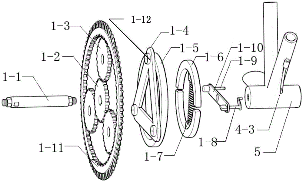
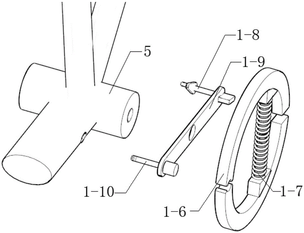
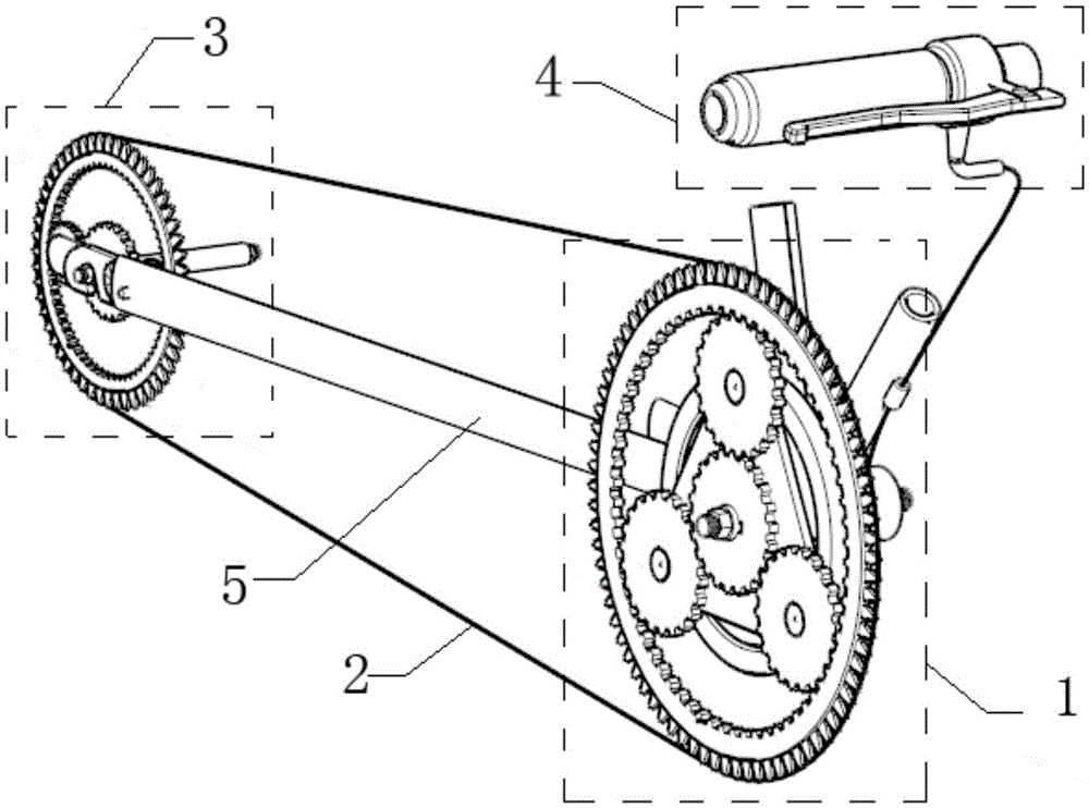
[0017] Implementation Case 1: Combining figure 1 and figure 2 , a new type of bicycle linear transmission provided by the present invention includes a drive shaft 1-1, a sun gear 1-2, a planetary gear 1-3, a friction ring 1-5, a friction plate 1-6, a preload spring 1- 7. Friction plate separator 1-8, friction plate support frame 1-9, friction plate support frame fixing pin 1-10, ring gear 1-11 and planetary gear shaft 1-12. The sun gear 1-2 is installed on the driving shaft 1-1, and the planetary gear 1-3 is arranged between the ring gear 1-11 and the sun gear 1-2 and is connected to the inner teeth of the sun gear 1-2 and the ring gear 1-11 meshing, the planetary gear 1-3 is installed on the friction ring 1-5 through the planetary wheel shaft 1-12, and the friction plate 1-6 is installed in the friction ring 1-5, and the friction plate 1-6 is formed by the upper friction The resistance plate and the lower friction plate are composed of a pre-compressed spring 1-7 in the mi...

Embodiment example 2

[0020] Implementation Case 2: According to a new type of bicycle linear transmission device described in Example 1, the planet carrier 1-4 is fixed on one side of the friction ring 1-5, and the planet wheel shaft 1-12 is fixed on the planet carrier 1- 4, then the planetary wheel will drive the fixedly connected planetary carrier 1-4 and the friction ring 1-5 to rotate together, making the transmission more reliable and stable.

Embodiment example 3

[0021] Example 3: According to Example 1 and Example 2, according to a new type of bicycle linear transmission device, there are three planetary gears 1-3, and there are three corresponding planetary wheel shafts 1-12, and the planetary carrier 1-4 It is an equilateral triangle structure, and the planetary gear shaft 1-12 is fixed at the three vertices of the triangular structure, then the sun gear 1-2 drives the three planetary gears 1-3 whose axes are distributed in an equilateral triangle to rotate, and the planetary gear 1-3 drives the solid The connected planet carrier 1-4 and the friction ring 1-5 rotate together, and the triangular structure makes the structure more firm and reliable.

[0022] Planetary gear 1-3 among the present invention can be one, two, three or four, as long as be installed on the planetary gear shaft 1-12 of corresponding number, planetary gear shaft 1-12 can be arranged on the friction circle 1-5 , can also be arranged on the planet carrier 1-4 fi...


PUM


Abstract

The invention provides a novel linear transmission device for bicycles, which includes a drive shaft, a sun wheel, a planetary wheel, a friction ring, a friction plate, a preload spring, a friction plate separator, a friction plate support frame, and a friction plate support frame The fixed pin and the ring gear, the sun gear is installed on the driving shaft, the planetary gear is arranged between the ring gear and the sun gear and meshes with the internal teeth of the sun gear and the ring gear, the planetary gear is installed on the friction ring through the planetary gear shaft, and the friction ring The resistance plate is installed in the friction ring. The friction plate is composed of upper and lower friction plates, and a pre-loaded spring is set in the middle, and a square gap and a circular gap are formed at both ends. One end of the friction plate support frame is installed with a circular The friction plate support frame fixing pin of the shaft, the other end is installed with a square block friction plate separator, the circular shaft end of the friction plate fixing pin is installed at the circular gap of the friction plate, and the other end is installed on the frame , the square block end of the friction plate separator extends into the shaped notch of the friction plate. The invention can realize linear speed change, instant speed change and stable speed change.

Description

technical field [0001] The invention relates to a speed change device of a vehicle, in particular to a linear speed change device for a bicycle. Background technique [0002] Bicycles have the characteristics of no noise, no pollution, light weight, small size, and easy placement. They can be used not only as a means of transportation and carrying light goods, but also for physical exercise. They are one of the most frequently used means of transportation in people's daily life. one. Since 1902, Britain's Stormy-Archer company installed a speed changer on the rear wheel of the bicycle, and the variable speed bicycle appeared. The variable-speed bicycle has a set of gears of different specifications in the rear wheel hub of the bicycle. When the bicycle is moving, the chain can be placed on different gears through the gearshift, thereby changing the speed of the bicycle to adapt to different road conditions and the physical strength of the rider. At present, most of the spe...

Claims


Application Information

Patent Timeline
Patent Type & Authority Patents(China)
IPC IPC(8): B62M11/14B62M11/18B62M25/04
Inventor 王振清刘艳龙孟庆华罗广龙
Owner HARBIN ENG UNIV
Why Eureka
Try Eureka