
Windshield for road traffic

A road traffic and blocking technology, applied in construction, protective equipment, etc., can solve the problems of inconvenient installation and transportation, rising cost of windshield devices, and inability to ensure safety in train operation.

Inactive Publication Date: 2014-09-03
CENT SOUTH UNIV
View PDF7 Cites 14 Cited by
  • Summary
  • Abstract
  • Description
  • Claims
  • Application Information

AI Technical Summary

Problems solved by technology

[0004] Although installing windshields on both sides of railways and highways can reduce wind speed and improve train operation safety and operation capacity, three problems need to be solved when installing windshields: (1) the windshielding efficiency of windshields; (2) the effect of strong winds The stability of the lower windshield structure itself; (3) Due to the addition of windshields on the bridge structure, the shape coefficient of the bridge structure will be changed, resulting in a substantial increase in the wind load acting on the bridge, reducing the wind-induced safety of the bridge structure
[0005] At present, the windshield adopts a solidified structure, which cannot adjust the wind force acting on the windshield at different wind speeds. Although the windshield efficiency is high, the windshield is too large to face the wind, and the wind load acting on the windshield device is too large
In order to ensure that the windshield device will not be damaged under the action of strong wind, the windshield device needs to be made very rigid, but this will lead to a substantial increase in the cost of the windshield device, and it is inconvenient to install and transport
If the opening ratio of the windshield is too large, although the wind load acting on the windshield can be reduced, the windshield device’s wind blocking efficiency cannot be effectively guaranteed, resulting in no safety guarantee for train operation when the wind speed is too high effect

Method used


Image

  • Windshield for road traffic
  • Windshield for road traffic
  • Windshield for road traffic

Examples


Embodiment Construction

[0053] The following is a further description of the technical content of the patent of the present invention, but it is not a limitation to the essential content of the patent of the present invention.

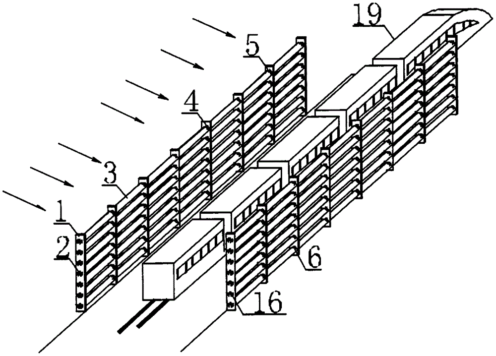
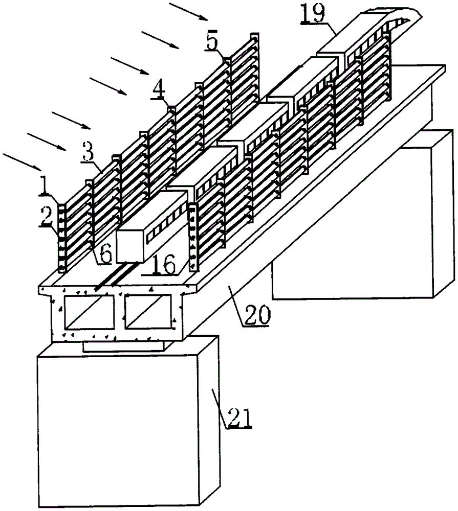
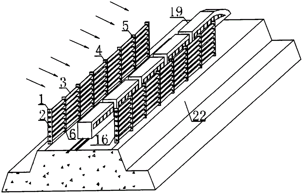
[0054] The windshield for road traffic includes a frame, and at least one windshield 3 is installed in the frame to control the windshield rate through rotation. The two ends of the windshield 3 are provided with a rotating shaft 4 for the rotation of the windshield 3, and a pivot is provided on the frame. The connecting hole 2 and the rotating shaft 4 are matched with the pivoting hole 2 , the windshield 3 rotates on the frame through the rotating shaft 4 , and the frame is also provided with a rotation limiting structure for restricting the rotation of the windshield 3 . The windshield for road traffic, when the side wind blows on the windshield, the wind pressure will generate an unbalanced rotational moment on the windshield 3, which drives the windshield 3 to rotate aroun...


PUM


Abstract

The invention relates to a windshield for road traffic, which comprises a frame; at least one wind deflector for controlling the wind deflecting rate by rotating is arranged in the frame; rotating shafts for rotating the wind deflector are arranged at two ends of the wind deflector; pivot holes are formed in the frame; the rotating shafts are connected with the pivot holes in a matched manner; the wind deflector rotates on the frame through the rotating shafts; a rotation limiting structure for limiting rotation of the wind deflector is also arranged on the frame. The windshield for road traffic, which is disclosed by the invention, is simple in structure, economic, practical and good in windshield effect; the wind deflector is capable of automatically adjusting the ventilation efficiency of the windshield under the action of unbalanced moment generated by wind pressure according to different wind speeds; in addition, safety of a windshield structure and a bridge structure is ensured while the wind speed is reduced and safety operation of vehicles is ensured.

Description

technical field [0001] The invention relates to the technical field of road traffic safety equipment, in particular to a windshield for road traffic. Background technique [0002] With the rapid development of high-speed railways, due to the high speed of high-speed trains and the reduction of axle load, the safety of train operation under the action of cross wind has become increasingly prominent. Under the action of strong crosswinds, the aerodynamic performance of the train deteriorates, and the air resistance, lift and lateral force of the train increase rapidly, which will cause the train to derail or overturn in severe cases. In December 2005 and September 2006, Japan's Shinkansen high-speed trains experienced two train overturning incidents caused by strong winds. In February 2007, a major accident occurred in Xinjiang, my country, in which 11 train carriages were overturned by strong winds. In 2013, my country's Beijing-Shanghai high-speed railway also caused vehic...

Claims


Application Information

Patent Timeline
Patent Type & Authority Applications(China)
IPC IPC(8): E01F7/02
Inventor 朱志辉
Owner CENT SOUTH UNIV
Learn More