Dam seepage pressure measuring device

A pressure measuring device and seepage technology, which is applied in the field of foundation soil survey, construction, infrastructure engineering, etc., can solve the problems of inconvenient pressure measuring tubes, high requirements for sealing technology, and increasing pressure measuring tubes, so as to reduce sealing Possibility of failure, simplified adjustment workload, effect of improved accuracy

Active Publication Date: 2014-09-10
NANJING HYDRAULIC RES INST
View PDF6 Cites 2 Cited by
  • Summary
  • Abstract
  • Description
  • Claims
  • Application Information

AI Technical Summary

Problems solved by technology

Traditional piezometric tubes have many parts that need to be sealed, which not only has high requirements on the sealing process, but also increases the probability of piezometric tube failures and deviations in measured values
[0004] In addition, the traditional piezometer is fixed by a cable passing through the orifice hole. As time goes by and the orifice relaxes, the cable is easily loosened and deformed, causing the elevation of the piezometer to change and thus affecting the accuracy of the measurement data. It is not convenient to correct and adjust the length of the cable in the piezometric tube in the dam site environment, and the entire piezometric tube can only be replaced, which takes time and effort and causes economic waste

Method used


Image

  • Dam seepage pressure measuring device
  • Dam seepage pressure measuring device
  • Dam seepage pressure measuring device

Examples


Embodiment

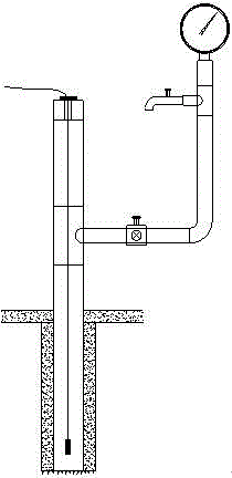
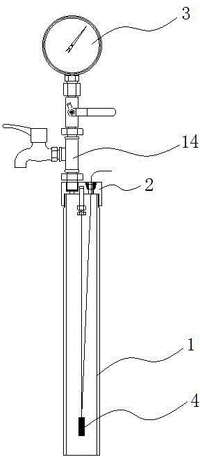
[0021] according to figure 2 with image 3 As shown, the embankment seepage pressure measuring device in the present invention includes a piezometric tube 1 , a top end cover 2 , a pressure gauge 3 and a piezometer 4 .

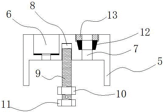
[0022] Wherein, the top end cover 2 is used to cover the top opening of the pressure measuring tube 1, and the edge of the top end cover 2 is provided with an outer skirt 5 extending toward the direction of the pressure measuring tube 1 and used to cover the surface of the pressure measuring tube 1. 5 and the pressure measuring tube 1 are connected by thread. The end cover 2 is provided with a first through hole 7 and a second through hole 6 .

[0023] Wherein, the pressure gauge 3 is located outside the pressure measuring tube 1 and connected to the second through hole 6 through a pipe joint. The pipe joint is composed of a three-way pipe 14, a pipe coupler, a control valve and a drain tap. One end of the main pipe on the three-way pipe 14 is connected to...


PUM


Abstract

The invention relates to a dam seepage pressure measuring device. The dam seepage pressure measuring device comprises pressure measuring tubes with top end covers, pressure gages connected with the top end covers and osmotic pressure gauges hung in the pressure measuring tubes, wherein first through holes are formed in the top end covers, cables connected with the osmotic pressure gauges pass through the first through holes and extend to the exteriors of the pressure measuring tubes, inner thread blind holes which are respectively opened towards the pressure measuring tubes are formed in the top end covers, bolts are respectively screwed in the inner thread blind holes, the precession depth of a threaded rod portion of each bolt in each inner thread blind hole is less than the maximum designed screwing depth of each inner thread blind hole, a suspending cable is arranged at the bottom of each bolt, and the bottom of each suspending cable is fixed on each osmotic pressure gauge. According to the dam seepage pressure measuring device, the number of the pressure measuring tubes, which need to be sealed, is decreased, the bolts are virtually connected in the inner thread blind holes and matched with gauge points, and therefore adjustment workload is greatly reduced, and adjustment accuracy is improved.

Description

technical field [0001] The invention relates to a dam seepage pressure measuring device, which belongs to the field of water conservancy engineering. Background technique [0002] There are a large number of dams in our country, and their safety is related to the safety of people's lives and properties downstream. It is very urgent to determine whether the infiltration line data in the dam body can be stably and reliably measured and real-time mastered, which is an important basis for the analysis of dam safety. According to the provisions of the current "Code for Design of Embankment Engineering" GB50286-98 and "Code for Design of Rolling Earth-rock Dams" SL274-2001 in water conservancy projects: in order to monitor the safe operation of embankments and earth-rock dams, dikes with a grade of 2 or above and grades in the For dams with a height of more than 30m at levels 3, 4, and 5, seepage observation facilities should be installed to observe and grasp the dam seepage line ...

Claims


Application Information

Patent Timeline
Patent Type & Authority Applications(China)
IPC IPC(8): E02D1/00
Inventor 马福恒李子阳戴群胡江何文洲周海啸
Owner NANJING HYDRAULIC RES INST
Why Eureka
Try Eureka