Object information obtaining method and electronic device

An electronic device and acquisition method technology, applied in the electronic field, can solve the problem of low acquisition rate of target object information, achieve the effect of increasing information acquisition rate, reducing calculation amount, and increasing acquisition rate

Active Publication Date: 2014-09-10
LENOVO (BEIJING) LTD
View PDF11 Cites 24 Cited by
  • Summary
  • Abstract
  • Description
  • Claims
  • Application Information

AI Technical Summary

Problems solved by technology

[0006] The embodiment of the present invention provides a target object information acquisition method and electronic equipment, which are used to solve the technical problem of low target object information acquisition rate in the prior art, and realize the technical effect of increasing the information acquisition rate

Method used


Image

  • Object information obtaining method and electronic device
  • Object information obtaining method and electronic device
  • Object information obtaining method and electronic device

Examples


Embodiment 1

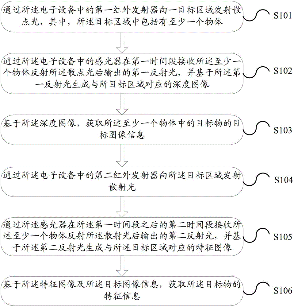
[0059] Please refer to figure 1 Embodiment 1 of the present application provides a method for acquiring target information, which is applied to an electronic device, and the method includes:

[0060] S101: Emit scattered light to a target area through a first infrared emitter in the electronic device, where at least one object is included in the target area.

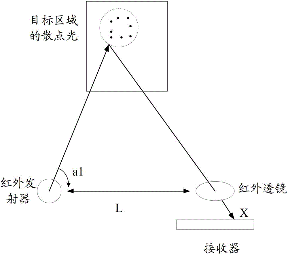
[0061] In the specific implementation process, in order to obtain the depth image of the target area, it is often necessary to emit scattered light with a certain shape to the target area, such as a circle, a square, etc. The scattered light specifically refers to light distributed in a point shape , the light source of the scattered light can be an ordinary white light source or an infrared light source, because infrared light has strong penetrating power to the clouds and fog in the air, and is easy to control, so in the current non-contact measurement technology Basically all use infrared light source. When the infr...

Embodiment 2

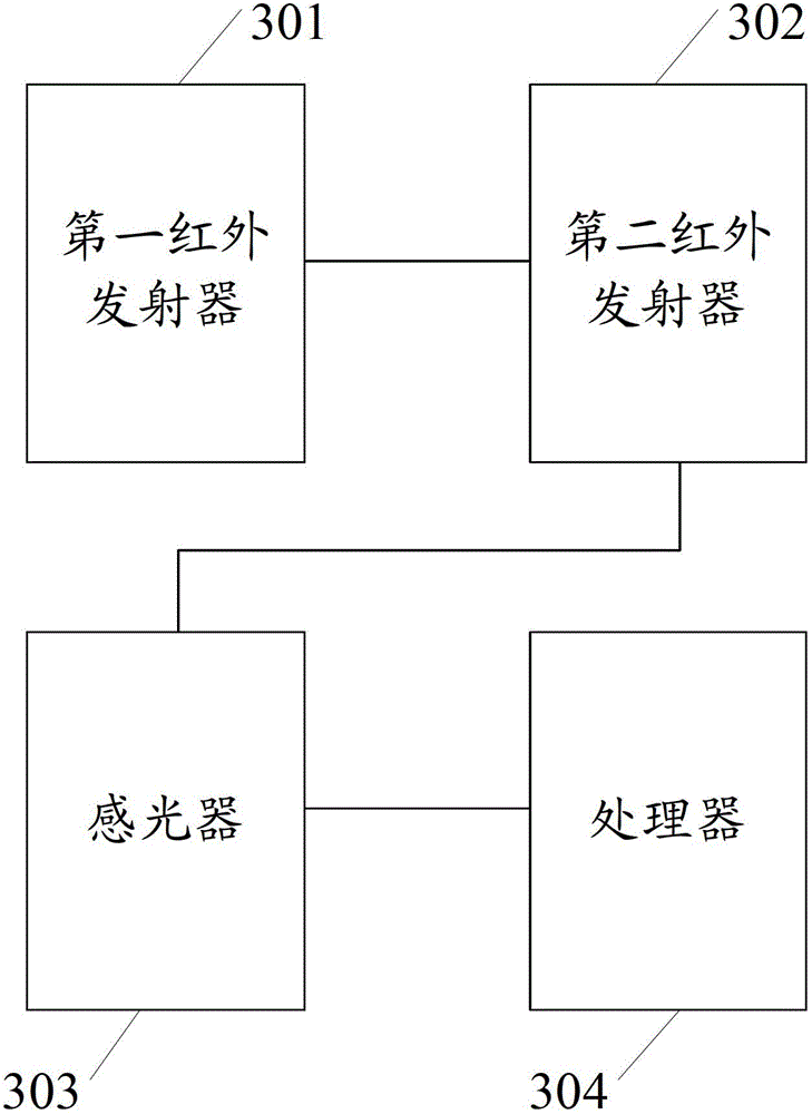
[0087] Please refer to image 3 , the embodiment of the present application also provides an electronic device, including:

[0088] The first infrared emitter 301 is configured to emit scattered light to a target area, wherein the target area includes at least one object;

[0089] a second infrared emitter 302, configured to emit scattered light to the target area;

[0090] The photoreceptor 303 is configured to receive the first reflected light outputted by the at least one object after emitting the scattered light in the first time period, and generate a depth image corresponding to the target area based on the first reflected light, receiving second reflected light output by the at least one object after reflecting the scattered light in a second time period after the first time period, and generating a feature image corresponding to the target area based on the second reflected light;

[0091] The processor 304 is configured to acquire target image information of a targe...


PUM


Abstract

Disclosed are a target object information acquisition method and an electronic device. The target object information acquisition method comprises: a first infrared transmitter transmitting scatter light to a target area comprising at least one object; a photoreceptor receiving first reflected light output after at least one object reflects the scatter light in a first time period, and generating a depth image corresponding to the target area based on the first reflected light; based on the depth image, acquiring the target image information about a target object from amongst at least one object; a second infrared transmitter transmitting scatter light to the target area; the photoreceptor receiving second reflected light output after at least one object reflects the scatter light in a second time period after the first time period, and generating a feature image corresponding to the target area based on the second reflected light; and based on the feature image and target image information, acquiring feature information about the target object. By means of the time division multiplexing of the same photoreceptor, the present invention solves the technical problem of a low acquisition rate for target object information in the prior art, and the information acquisition rate is improved.

Description

technical field [0001] The invention relates to the field of electronic technology, in particular to a method for acquiring target information and electronic equipment. Background technique [0002] With the continuous development of science and technology, object tracking and depth measurement technologies are developing rapidly, and are widely used in high-speed online monitoring, robot vision, medical diagnosis and other fields. Among the methods of object tracking and depth measurement technology, the optical measurement method with non-contact characteristics is widely popular due to its advantages of high resolution, non-destructiveness, and fast data acquisition speed. [0003] A single optical measurement method cannot obtain the texture characteristics of the target object at the time of object tracking or depth measurement. In order to solve this technical problem, the existing technology provides a solution: two sets of measurement equipment are used at the same t...

Claims


Application Information

Patent Timeline
Patent Type & Authority Applications(China)
IPC IPC(8): G06K9/00G01B11/30G01B11/24G06V10/141G06V10/10
CPCG06K9/00G01S17/48G01S17/50G01S17/89G01S7/4814G01S17/86G06V10/141G06V10/10G06V40/161G06V40/172G01B11/22H04N5/33
Inventor 阳光姚健
Owner LENOVO (BEIJING) LTD
Why Eureka
Try Eureka