Restrictor and production process of a fluid leakage restrictor for aerostatic bearings

A production process, technology of restrictors, applied to components, shafts and bearings, air cushion bearings, etc. of pumping devices for elastic fluids, capable of solving problems such as undiscovered restrictor solutions

Inactive Publication Date: 2014-09-10
WHIRPOOL SA
View PDF11 Cites 8 Cited by
  • Summary
  • Abstract
  • Description
  • Claims
  • Application Information

AI Technical Summary

Problems solved by technology

[0015] In any case, a solution that guarantees the production of constant-flow microtube-based restrictors has not yet been found

Method used


Image

  • Restrictor and production process of a fluid leakage restrictor for aerostatic bearings
  • Restrictor and production process of a fluid leakage restrictor for aerostatic bearings
  • Restrictor and production process of a fluid leakage restrictor for aerostatic bearings

Examples


Embodiment Construction

[0040] The present invention presents technological advances at the level of restrictors (better known by those skilled in the art as restrictor tubes / microtubes) and the production process that yields restrictors with desired fluid flow characteristics.

[0041] According to the working principle of the cooling circuit and as in figure 1 As shown in , the gas compression mechanism preferably takes place by the axial and oscillatory movement of the piston 1 inside the cylinder 2 . At the top of the cylinder 2 is a cylinder head 3 which, in conjunction with the piston 1 and cylinder 2 , forms a compression chamber 4 . A discharge valve 5 and a suction valve 6 , which regulate the inflow and outflow of gas in the cylinder 2 , are positioned in the cylinder head 3 . It should also be noted that the piston 1 is driven by an actuator 7 coupled to the linear motor of the compressor. Further explanation of such motors is not provided herein.

[0042] The piston 1 of the compressor...


PUM


Abstract

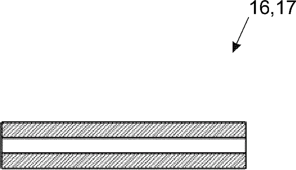
The present invention pertains to restrictors (16,17) for aerostatic bearings capable of guaranteeing a constant flow, regardless of their size and dimensional tolerance, such that the gas flow is adjusted by means of deforming their internal section. Additionally, there is also provided a process capable of guaranteeing the production of restrictors (16,17) for aero- static bearings with respect to guaranteeing the gas flow values desired.

Description

technical field [0001] The invention relates to a limiter for the aerostatic bearing of a piston in a cylinder comprised by a linear compressor for cooling. Background technique [0002] Generally speaking, the basic structure of a cooling circuit includes four components, namely a compressor, a condenser, an expansion device, and an evaporator. These elements are characterized by a cooling circuit in which a fluid circulates in order to allow the temperature of the internal environment to decrease, to extract heat from the internal environment, and to remove the heat to the external environment through the elements constituting the cooling circuit. [0003] The fluid circulating in the cooling circuit generally follows the following pass sequence: compressor, condenser, expansion valve, evaporator and again through the compressor, thus characterizing a closed cycle. During the cycle, the fluid undergoes pressure and temperature changes that cause a change in the state of t...

Claims


Application Information

Patent Timeline
Patent Type & Authority Applications(China)
IPC IPC(8): F04B35/04F04B39/12F04B53/16F16C29/02F25B31/02F16C32/06
CPCF04B35/04F04B53/162F04B53/18F25B31/023F16C29/025B21D31/06F04B35/045F04B39/122Y10T29/49771F04B53/166F04B39/126F16C32/0622
Inventor H.布雷格曼恩梅勒D.E.B.里里伊
Owner WHIRPOOL SA
Why Eureka
Try Eureka