
Method for operating motor vehicle

A technology for motor vehicles and machinery, applied in the field of clutch systems, which can solve problems such as troublesome operation schemes

Inactive Publication Date: 2014-10-01
ROBERT BOSCH GMBH
View PDF10 Cites 0 Cited by
  • Summary
  • Abstract
  • Description
  • Claims
  • Application Information

AI Technical Summary

Problems solved by technology

However this requires a cumbersome operational scheme

Method used


Image

  • Method for operating motor vehicle
  • Method for operating motor vehicle
  • Method for operating motor vehicle

Examples


Embodiment Construction

[0034] The invention is illustrated schematically with the aid of an embodiment in the drawing and will be explained in more detail below with reference to the drawing.

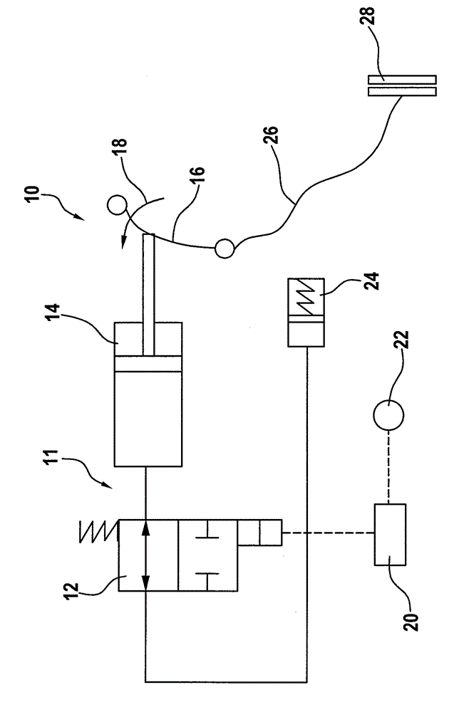
[0035] figure 1 An embodiment of a clutch system, designated generally by the reference number 10 , is shown, which has a hydraulic unit 11 . The drawing shows: a valve 12 , a cylinder 14 , a clutch lever 16 as a clutch actuating element, the actuation of which is indicated by an arrow 18 , an engine control unit or control unit 20 , a display light on the instrument panel or a coasting display light 22, accumulator 24, control lock 26 and clutch 28. Therefore, only a control lock is provided between the clutch lever 16 as clutch actuating element and the clutch in order to transmit the force exerted on the clutch lever 16 . The control lock provides a mechanical, in particular purely or exclusively mechanical, path of action.

[0036] Clutch 28 is used to releasably rotationally rigidly or elastically conne...


PUM


Abstract

The invention relates to a method and system for operating motor vehicle. A motor vehicle has a clutch system (10). The clutch system is used for transmitting a force applied on a clutch operation element to a clutch (28) only mechanically. The clutch (28) is opened through operation of the clutch operation element. The clutch (28) is kept open through a hydraulic unit (11) arranged additionally.

Description

technical field [0001] The invention relates to a method for operating a motor vehicle and a clutch system for carrying out the method. The method is used in a motor vehicle having a clutch system for mechanically transmitting a force exerted by a driver on a clutch actuating element to a clutch. Background technique [0002] The mechanical transmission of the force exerted by the driver takes place, for example, by means of a control lock. Such clutch systems are commonly used in two-wheeled vehicles. However, such mechanical transmissions are also used in other motor vehicles, for example passenger cars or trucks. [0003] It should be noted that a distinction is made between different driving states of the motor vehicle. One driving state known as coasting is already known in hybrid vehicles, for example in parallel hybrid drives with a disconnect clutch between the internal combustion engine and the electric drive machine. However, it has turned out that coasting can...

Claims


Application Information

Patent Timeline
IPC IPC(8): F16D48/02
CPCF16D48/06F16D2048/0212F16D2048/0269F16D2500/1117F16D2500/3067F16D2500/31426F16D2500/3144F16D2500/3146F16D2500/5085F16D2500/7041F16D2500/7104
Inventor P.阿南塔B.海因茨曼
Owner ROBERT BOSCH GMBH
Learn More