Charging system and charging method

A charging system and charging interface technology, applied in the field of power supply, can solve the problem of not long-lasting battery life, and achieve the effect of long-lasting charging and battery life

Active Publication Date: 2014-10-01
TENCENT TECH (SHENZHEN) CO LTD
View PDF4 Cites 1 Cited by
  • Summary
  • Abstract
  • Description
  • Claims
  • Application Information

AI Technical Summary

Problems solved by technology

[0004] The purpose of the embodiments of the present invention is to provide a charging system to solve the problem in the prior art that using a mobile power supply to charge the battery does not last long

Method used


Image

  • Charging system and charging method
  • Charging system and charging method
  • Charging system and charging method

Examples


Embodiment 1

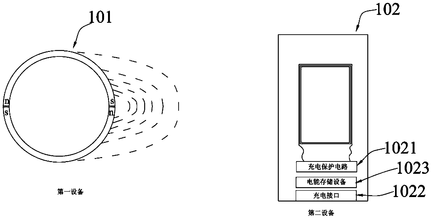
[0016] figure 1 It shows the structural diagram of the charging system provided by the first embodiment of the present invention, and the details are as follows:

[0017] The charging system according to the embodiment of the present invention includes a first device 101 with a magnetic medium, a second device 102 that can sense the change in magnetic flux and convert the change in magnetic flux into electric energy, and the second device is provided with a pair of The charging protection circuit 103 for limiting the converted electric energy and the charging interface 104 that can be connected to the device to be charged, the charging protection circuit 103 is connected to the charging interface 104 .

[0018] Wherein, the first device 101 has a magnetic medium, magnetic materials or other devices that can generate magnetic lines of induction can be set in the first device, such as NdFeB magnets in permanent magnets, because they have very strong magnetism, they can When mak...

Embodiment 2

[0028] Such as Figure 4 The schematic structural diagram of the charging system provided by the second embodiment of the present invention is described in detail as follows:

[0029] The charging system according to the embodiment of the present invention, the charging system includes a first device 401 with a magnetic medium 4013, a second device 402 that can sense the change in magnetic flux and convert the change in magnetic flux into electrical energy, the first The second device 402 is provided with a charging protection circuit 4021 that limits the converted electric energy and a charging interface 4022 that can be connected to the device to be charged. The charging protection circuit 4021 is connected to the charging interface 4022 . In addition, the first device 401 also includes a power conversion circuit 4011 capable of sensing the change in magnetic flux and converting the change in magnetic flux into electric energy, and a display device 4012 connected to the powe...

Embodiment 3

[0036] This embodiment is a charging method based on the charging system described in the above two embodiments, and is described in detail as follows:

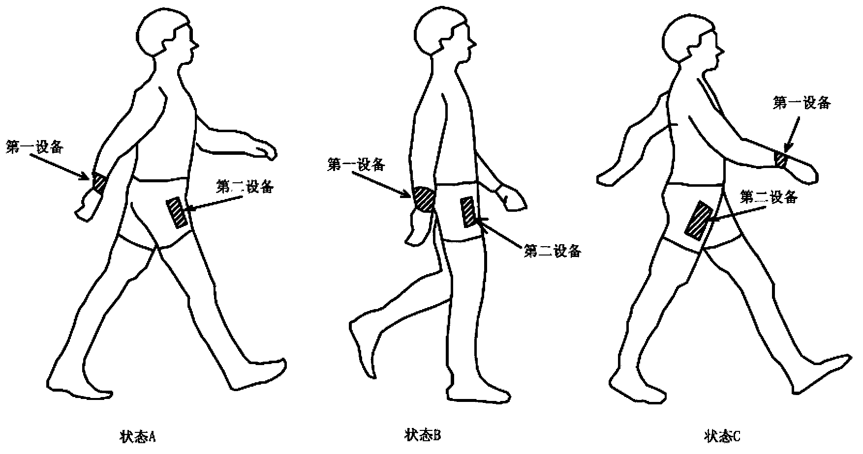
[0037] In the charging system described in the first embodiment above, correspondingly, the method includes: setting the first device and the second device to reciprocate in opposite directions, so that the magnetic induction lines of the first device pass through the second device When the magnetic flux changes, the second device converts the sensed and changed magnetic flux into electrical energy, and connects it to the charging interface through the charging protection circuit, so that the device to be charged receives the converted electrical energy.

[0038] When the charging system further includes an electrical energy storage device, the method further includes:

[0039] The second device stores the converted electric energy in the electric energy storage device, and when the device to be charged needs to be charged, t...


PUM


Abstract

The invention is applicable to the field of charging, and provides a charging system and a charging method. The charging system comprises first equipment with a magnetic medium, and second equipment which can sense flux change quantity and convert the flux change quantity into electric energy, wherein the second equipment is provided with a charging protection circuit for limiting the converted electric energy, and a charging interface connected with to-be-charged equipment; and the charging protection circuit is connected with the charging interface. Due to change of a relative position between the first equipment and the second equipment, the second equipment can generate the flux change quantity and convert the flux change quantity into the electric energy; and the charging protection circuit is connected with the charging interface, so that the converted electric energy can be transmitted to the to-be-charged equipment by the charging interface. According to the charging system and the charging method, the charging endurance power is not influenced by limited battery capacity, so that true and persistent charging endurance is achieved.

Description

technical field [0001] The invention belongs to the field of power supplies, and in particular relates to a charging system and a charging method. Background technique [0002] With the rise of mobile devices, people's requirements for power sources are getting higher and higher. On the one hand, efforts are being made to develop battery capacity to provide mobile devices with longer battery life. On the other hand, corresponding mobile power sources have also been developed. Through An additional power source is carried, and the battery of the mobile device is charged by the additional power source, so as to increase the use time of the mobile device outdoors. [0003] However, in order to increase the charging capacity of the existing mobile power supply or the battery of the mobile device, the volume and quality of the battery need to be increased. While it is inconvenient to carry, it cannot provide a long-lasting battery life for the mobile device and cannot really solv...

Claims


Application Information

Patent Timeline
Patent Type & Authority Applications(China)
IPC IPC(8): H02K35/00
CPCH02K35/02H02J7/0029H02J7/007H02J7/025Y02B40/90H02J7/32H02J7/0044H02J50/10H02J7/00308H02J7/00304
Inventor 罗亮俊
Owner TENCENT TECH (SHENZHEN) CO LTD
Why Eureka
Try Eureka