TWS Bluetooth headset charging system

A charging system, a technology for Bluetooth headsets, applied in the directions of mechanical/electronic switches for headsets, stereo communication headsets, earpieces/headset accessories, etc., can solve the problems of inability to maintain battery life, low storage power, and inconvenient use.

Pending Publication Date: 2021-04-23
LUXSHARE ELECTRONICS TECH (KUNSHAN) LTD
View PDF0 Cites 2 Cited by
  • Summary
  • Abstract
  • Description
  • Claims
  • Application Information

AI Technical Summary

Problems solved by technology

[0005] For this reason, the present invention provides a kind of TWS bluetooth earphone charging system, by arranging solar secondary charging system to TWS bluetooth earphone charging device, ca...

Method used


Image

  • TWS Bluetooth headset charging system
  • TWS Bluetooth headset charging system
  • TWS Bluetooth headset charging system

Examples


Embodiment 1

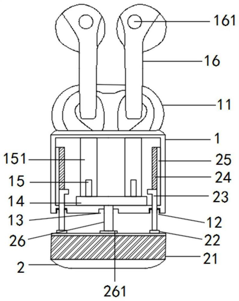
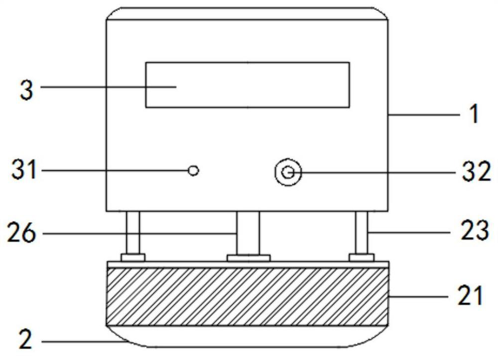
[0027] Refer to attached Figure 1-Figure 5 , a TWS Bluetooth headset charging system of this embodiment, including a charging stand 1, a battery stand 2, a display screen 3 and a charging system 4;

[0028] Further, the inner wall of the charging stand 1 is fixed with a sliding seat 25, the inner wall of the sliding seat 25 is provided with a chute 24, the inner wall of the chute 24 is inserted into the sliding rod 23, and the lower side of the charging stand 1 is provided with the battery Seat 2, the lower end of the slide bar 23 is fixedly connected to the battery seat 2, the outer wall of the battery seat 2 is fixedly installed with solar cells 21, the upper end of the battery seat 2 is fixedly installed with a power transmission rod 26, and the lower end of the charging seat 1 is opened The second through hole 131, the power transmission rod 26 passes through the second through hole 131, the upper end of the power transmission rod 26 is fixedly installed with the contact ...

Embodiment 2

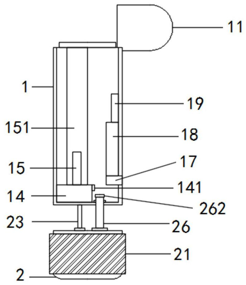
[0037] Refer to attached Figure 6 , a TWS Bluetooth headset charging system of this embodiment, including a charging stand 1, a battery stand 2, a display screen 3 and a charging system 4;

[0038] Further, the upper end of the battery holder 2 is fixed with a plug 27, the plug 27 has the function of fixing the battery holder 2, and the side end of the charging stand 1 is provided with a slot 123, and the slot 123 has the function of fixing the plug 27.

[0039] The use process of the present invention is as follows: when using the present invention, the inner wall of the charging stand 1 is fixedly installed with a sliding seat 25, and the charging stand 1 has the function of charging the TWS Bluetooth earphone 16, which can be charged at any time outdoors, and the sliding seat 25 has a positioning slide bar 23 position The inner wall of the sliding seat 25 is provided with a chute 24. The chute 24 has the function of facilitating the insertion of the sliding bar 23 to slide...


PUM


Abstract

The invention discloses a TWS Bluetooth earphone charging system, and particularly relates to the technical field of Bluetooth earphones, and the technical scheme is that the TWS Bluetooth earphone charging system comprises a charging seat, a battery seat, a display screen and a charging system; a sliding seat is fixedly installed on the inner wall of the charging seat, a sliding groove is formed in the inner wall of the sliding seat, and a sliding rod is inserted into the inner wall of the sliding groove; the lower side of the charging seat is provided with the battery seat; the lower end of the sliding rod is fixedly connected with the battery holder, a solar battery piece is fixedly installed on the outer wall of the battery holder, a power transmission rod is fixedly installed at the upper end of the battery holder, a second through hole is formed in the lower end of the charging base, and the power transmission rod penetrates through the second through hole. The TWS Bluetooth headset charging device has the beneficial effects that the TWS Bluetooth headset charging device is provided with the solar secondary charging system, so that the TWS Bluetooth headset can use the standby battery powered by solar energy under the condition that the electric quantity of the original battery is used up, and the TWS Bluetooth headset charging device is energy-saving, environment-friendly and lasting in endurance.

Description

technical field [0001] The invention relates to the field of bluetooth earphones, in particular to a TWS bluetooth earphone charging system. Background technique [0002] TWS Bluetooth headset is a true wireless stereo headset. TWS technology is also based on the development of Bluetooth chip technology. According to its working principle, the mobile phone is connected to the main headset, and then the main headset is quickly connected to the secondary headset wirelessly. The left and right channels of Bluetooth are used wirelessly. When the slave earphone is not connected, the main earphone returns to mono sound quality. [0003] The existing technology has the following deficiencies: the existing TWS Bluetooth headset charging device stores less power, cannot continue the battery life, and can charge the headset twice at most, which is inconvenient to use outdoors. [0004] Therefore, it is necessary to invent a TWS Bluetooth headset charging system. Contents of the inv...

Claims


Application Information

Patent Timeline
IPC IPC(8): H04R1/10H04R5/033H02J7/00H02J7/35
CPCH02J7/0044H02J7/35H04R1/1025H04R1/1041H04R5/033H04R2201/10Y02E10/56
Inventor 张鸿吴静刘波
Owner LUXSHARE ELECTRONICS TECH (KUNSHAN) LTD
Why Eureka
Try Eureka