Passive thermal management device

A technology of thermal management and heat dissipation device, applied in indirect heat exchangers, heat exchange equipment, lighting and heating equipment, etc., can solve the problem of no longer allowing thermal management, and achieve the effect of improving thermal conductivity and large usable volume

Inactive Publication Date: 2014-10-01
COMMISSARIAT A LENERGIE ATOMIQUE ET AUX ENERGIES ALTERNATIVES
View PDF6 Cites 5 Cited by
  • Summary
  • Abstract
  • Description
  • Claims
  • Application Information

AI Technical Summary

Problems solved by technology

However, in transient regimes, when the heat flux is relatively high and the load duration is relatively short, this material no longer allows effective thermal management

Method used


Image

  • Passive thermal management device
  • Passive thermal management device
  • Passive thermal management device

Examples


Embodiment Construction

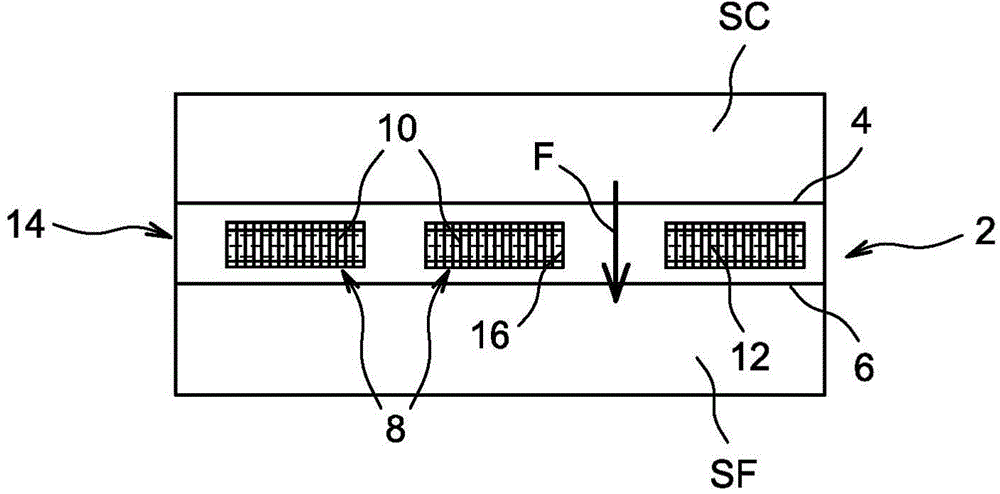
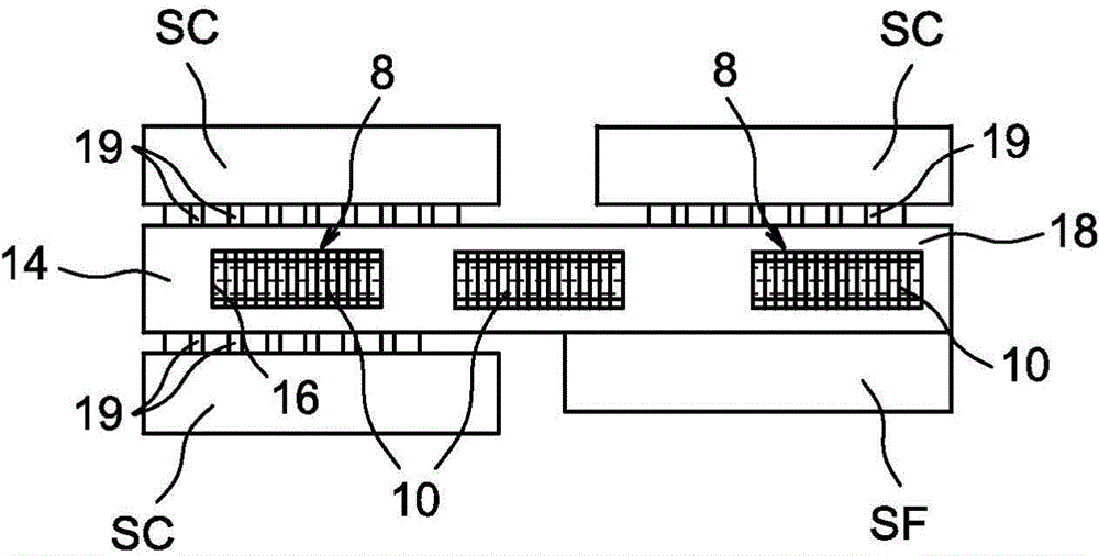
[0046] exist Figure 1A and Figure 1B , schematically shows an exemplary embodiment of a heat management device 2 in which a heat source SC and a heat sink SF are arranged.

[0047] For example, the heat source SC is an electronic system and the heat sink SF is a heat sink with cooling fins.

[0048] The substantially flat device comprises a first face 4 for contact with a heat source SC and a second face 6 opposite to the first face 4 for contact with a heat sink.

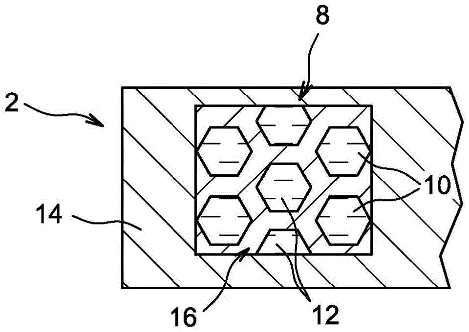
[0049]The device comprises a thermally conductive support 14 , for example made of monocrystalline silicon, in which a plurality of cavities 16 present in one face of the support 14 are produced. Each cavity 16 contains a network of cells 8 made of carbon nanotubes and a phase change material. Each cavity 16 is closed by a cover 18 . The first face 4 is formed by the cover 18 and the second face 6 is formed by the bottom of the support body 14 .

[0050] The device also comprises several unitary networks 8 ho...


PUM

PropertyMeasurementUnit
areaaaaaaaaaaa
areaaaaaaaaaaa
thicknessaaaaaaaaaa

Abstract

The invention provides a thermal management device, comprising a first face (4) intended to be in contact with a heat source (SC) and a second face (6) opposite the first face, intended to be in contact with a cold source (SF). At least one array of cells (8) filled with a solid-liquid phase-change material (10) is positioned in a recess between the first face (4) and the second face (6); the cells comprise walls formed from carbon nanotubes; and the nanotubes extend substantially from the first face (4) to the second face (6), thereby thermally connecting the first face (2) to the second face (4).

Description

technical field [0001] The present invention relates to a passive thermal management device that can be used, for example, to cool electronic components. Background technique [0002] More and more functions are confined to electronic systems. At the same time, reductions in the size of these components are sought. This tendency leads to an increase in heat dissipation per unit volume (or mass) of the element. [0003] Traditional cooling methods, such as air convection, whether natural or forced, are insufficient to evacuate this heat. [0004] When the heat flux is relatively high and the load duration is relatively short, in addition to a larger amount of heat to be dissipated, it also creates a heat dissipation problem in the transient state mode. [0005] It has been envisioned to integrate microchannels within elements associated with external active heat transfer fluid circulation systems. This technique is relatively efficient at removing heat while limiting the ...

Claims


Application Information

Patent Timeline
Patent Type & Authority Applications(China)
IPC IPC(8): H01L23/373H01L23/427
CPCH01L23/427F28D15/02H01L2924/0002B82Y99/00C23C16/26Y10S977/742Y10T29/49353H01L23/373C23C16/0236H05K7/2029B21D53/02C23C16/0272H01L2924/00
Inventor 杰罗姆·加文莱特让·第戎
Owner COMMISSARIAT A LENERGIE ATOMIQUE ET AUX ENERGIES ALTERNATIVES
Why Eureka
Try Eureka