Fault relay protection method for three-phase three-winding transformer based on positive sequence current mutation

A transformer fault and positive sequence current technology, applied in the direction of emergency protection circuit devices, electrical components, etc., can solve problems such as difficulty in finding fault points, low reliability, rapid elimination of unfavorable faults, and rapid restoration of power supply

Active Publication Date: 2017-02-15
STATE GRID PUTIAN ELECTRIC POWER SUPPLY +3
View PDF3 Cites 0 Cited by
  • Summary
  • Abstract
  • Description
  • Claims
  • Application Information

AI Technical Summary

Problems solved by technology

In order to eliminate the unbalanced current, the current compensation method of converting the two groups of Y-side currents to the △ side and the current compensation method of converting the △-side current to the two groups of Y-sides are mainly used at present, but the current difference between the two conversion methods is The momentum cannot correctly reflect the influence of the transformer excitation current, which affects the reliability of the current differential protection as the main protection of the transformer, and also makes the method of using the second harmonic to distinguish the excitation inrush current and short-circuit fault less reliable.
[0004] Affected by the limitations of the current differential protection principle, the current differential protection can only treat the three-phase three-winding transformer as a whole to be protected, and can only distinguish whether the fault point is located in the protection area, but cannot accurately determine whether the fault location is in the third Which side of the three-phase three-winding transformer cannot provide accurate fault range information for fault judgment, making it difficult to find the fault point after a fault, which is not conducive to rapid troubleshooting and rapid power supply recovery

Method used


Image

  • Fault relay protection method for three-phase three-winding transformer based on positive sequence current mutation

Examples


Embodiment Construction

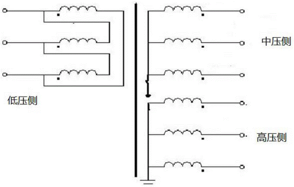
[0015] The technical solution of the present invention will be further described in detail according to the accompanying drawings.

[0016] figure 1 It is a schematic diagram of a Δ / Y / Y connection transformer applying the method of the present invention. In this embodiment, the protection device measures the sudden change of the positive sequence current of the φ phase on the high voltage side of the transformer respectively Sudden change in positive sequence current of φ phase at medium voltage side Sudden change in positive sequence current of φ phase at low voltage side Among them, φ=A, B, and C phases; h, m, and l represent the high-voltage side of the transformer, the medium-voltage side of the transformer, and the low-voltage side of the transformer, respectively.

[0017] Protection device judgment and and Whether it is true at the same time, if it is true at the same time, it is judged that the equipment in the protection area surrounded by the transformer ...


PUM


Abstract

The invention discloses a thee-phase three-winding transformer fault relay protection method based on sudden changes of positive sequence currents. Firstly, the sudden changes of the positive sequence currents on the high-voltage side, the medium-voltage side and the low-voltage side of a thee-phase three-winding transformer are measured, and the vector of the sudden change of the positive sequence current on the high-voltage side and the vector of the sudden change of the positive sequence current on the medium-voltage side are rotated 30 degrees counterclockwise respectively; secondly, a fault region of the thee-phase three-winding transformer is distinguished accurately according to the phase relation between the sudden change of the positive sequence current on the high-voltage side after counterclockwise rotation by 30 degrees, the sudden change of the positive sequence current on the medium-voltage side after counterclockwise rotation by 30 degrees and the sudden change of the positive sequence current on the low-voltage side. In the computing process, only the sudden changes of the positive sequence currents on the high-voltage side, the medium-voltage side and the low-voltage side of the transformer are utilized, there is no need to utilize thee-phase total currents on the three sides of the transformer, and motion performance is not affected by exciting currents or excitation inrush currents.

Description

technical field [0001] The invention relates to the technical field of electric power system relay protection, in particular to a fault relay protection method for a three-phase three-winding transformer based on positive sequence current mutation. Background technique [0002] 220kV transformers widely used in power systems usually use three-phase three-winding transformers. In order to ensure that the phase potential is close to the sine wave and provide a path for the third harmonic, a set of windings of the three-phase three-winding transformer must be connected in delta, so its connection method is △ / Y / Y connection. [0003] The current differential protection is the main protection of the transformer. In order to make the current differential amount zero during normal operation, it is necessary to convert the current of the two groups of Y sides of the transformer to the △ side or convert the current of the △ side to the two groups of Y sides to eliminate the imbalance...

Claims


Application Information

Patent Timeline
Patent Type & Authority Patents(China)
IPC IPC(8): H02H7/045
Inventor 曾惠敏林富洪
Owner STATE GRID PUTIAN ELECTRIC POWER SUPPLY
Why Eureka
Try Eureka