Command generating device and command generating method

A technology of command generation and command position, applied in position/direction control, electrical program control, instruments, etc., can solve problems such as reduced work efficiency and prolonged work takt time, and achieve the effect of avoiding interference actions and avoiding interference.

Active Publication Date: 2016-10-12
MITSUBISHI ELECTRIC CORP
View PDF5 Cites 0 Cited by
  • Summary
  • Abstract
  • Description
  • Claims
  • Application Information

AI Technical Summary

Problems solved by technology

However, according to this method, since the own axis needs to be on standby until the movement of the other axis is completed, there is a problem that the tact time of the controlled device is prolonged and the work efficiency is reduced.

Method used


Image

  • Command generating device and command generating method
  • Command generating device and command generating method
  • Command generating device and command generating method

Examples


Embodiment approach 1

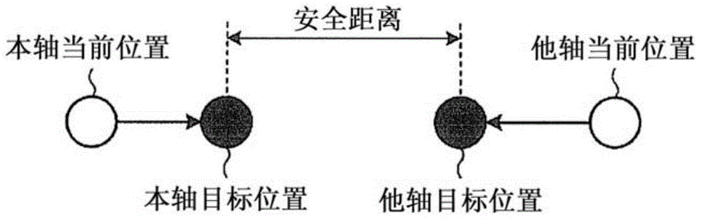
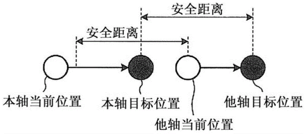
[0026] Picture 1-1 as well as Figure 1-2 It is a figure explaining the characteristic of the positioning operation performed by the command generation apparatus which concerns on Embodiment 1 of this invention. In addition, here, for simplicity of description, it is assumed that there are two movable axes (hereinafter, simply referred to as axes) included in the machine (controlled device) that is the control target of the command generation device (the own axis and the other axis).

[0027] Picture 1-1 An operation example in a case where the own axis (first movable axis) and the other axis (second movable axis) move in directions approaching each other is shown. According to the command generation device according to Embodiment 1, when the own axis and the other axes are moving in directions approaching each other, and when the distance between the target positions of both is greater than or equal to the safety distance, no interference avoidance is performed. control. ...

Embodiment approach 2

[0058] The command generation device according to Embodiment 2 can input a value not including the deceleration movement amount as the safety distance. Figure 8-1 as well as Figure 8-2 It is a figure explaining the safety distance used in Embodiment 2. As shown in the figure, even when the own axis and other axes move in a direction close to each other, or when the other axis moves in a direction away from the own axis, the offset between the axes can be used as a safety distance .


PUM


Abstract

In order to avoid interference without changing the operation mode of the movable shaft, the command generation device (100) has: a startup standby time calculation unit (110), which is based on the interference distance between the first movable shaft and the second movable shaft , and the operation mode of the first movable shaft and the second movable shaft, the distance between the two movable shafts is always greater than the interference distance during operation, and the first movable shaft Calculate the standby time of the operation start timing delay; and start the standby unit (120) and the command calculation unit (130), which function as the command output unit, and start to output the driving signal based on the operation mode of the second movable shaft. The command for the second movable shaft starts outputting the drive unit based on the operation mode of the first movable shaft when the calculated standby time elapses after the command for the second movable shaft is started to be output. Describe the command for the 1st movable axis.

Description

technical field [0001] The present invention relates to a command generation device and a command generation method for generating commands for driving various industrial machines (controlled devices) having a plurality of movable axes, such as mounting machines, machine tools, XY tables, robot arms, etc. instruction. Background technique [0002] When the movable areas of the plurality of movable shafts intersect with each other, it is necessary to perform positioning operation so that the movable shafts do not interfere with each other. As the simplest technique for performing a positioning operation so that a plurality of movable axes do not interfere, there is a method of starting the positioning operation of the own axis after moving the other axes to a position where they do not interfere. However, according to this method, since the own axis needs to stand by until the movement of the other axis is completed, there is a problem that the tact time of the controlled de...

Claims


Application Information

Patent Timeline
Patent Type & Authority Patents(China)
IPC IPC(8): G05B19/18G05D3/00
CPCG05B19/416
Inventor 高桥仁之丸下贵弘
Owner MITSUBISHI ELECTRIC CORP
Why Eureka
Try Eureka